Rotary encoder is an input device to help users interact with the system. It looks like a radio potentiometer, but it’s unique that it outputs a series of pulses.
The encoder rotates in small steps so that it is very suitable for many applications such as stepper / servo motor control, serial navigation menu, and increasing / decreasing digital values.
In this article, we will have a brief look at different types of encoders and how they work, and next get a closer look at how to connect a rotary encoder with Arduino board UNO. By controlling the value of integer through rotary encoder, we will display it on LCD 1602.
You will be familiar with using rotary encoders for your project. Let’s get start!
1. Components Required
* Rotary encoder (KY-040)* Arduino development board UNO
* LCD 1602
* 10K potentiometer
* Bread board
* Connecting wires
2. Working Principle of Rotary Encoder
Rotary encoder is a type of electromechanical transducer, which means it converts mechanical motion signal into electronic pulse. It consists of a knob that will move gradually when it is rotated, thus generating a series of pulses. There’s a a predefined width for each step. There are various types of encoders with their own working principle. But now let's just focus on the KY-040 incremental encoder used in our tutorial.
The internal mechanical structure of the encoder is shown as below. It consists of a disc (gray) and conductive pads (coppery) placed on the top of the disc. These conductive pads are placed at the same distance as shown below. There are two output pins, output A and output B, as shown in the figure below. The output pins are fixed on the top of the disc, so that when the knob rotates, the conductive pads will contact them.
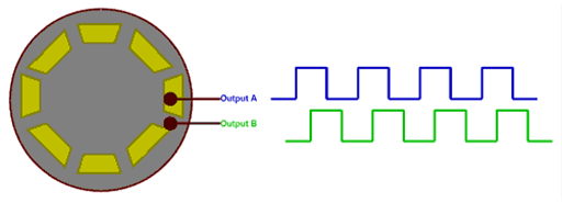
Figure 1: Output waveform of rotary encoder marked as output A and output B
The output waveform generated by output A and output B is displayed in blue and green respectively. The conductive pad is under the pin which will be higher and conducted. When the conductive pad is moved away, the pin will be lower, resulting in the end of the waveform shown as above.
Now, if we count the pulses, we will be able to determine how many steps the encoder has moved.
So why do we need two pulse signals instead of one pulse signal to calculate the number of steps taken to rotate the knob? The reason is that we want to determine the direction of the knob rotation. If you look at these two pulses, you will notice that they are both 90 °out of phase. Therefore, when the knob is rotated clockwise, the waveform of output A will rise first, and when counterclockwise, output B.
3. Types of Rotary Encoder
There are various rotary encoders on the market, and design engineers can choose one of them according to the actual application. The most common types are as follows.
* Incremental encoder
* Absolute encoder
* Magnetic encoder
* Optical encoder
* Laser encoder
These encoders are classified based on output signal and sensing technology. Incremental encoders and absolute encoders are identified based on output signal. Plus magnetic, optical and laser encoders are distinguished from sensing technology. In this tutorial, we have used an incremental encoder.
4. KY-040 Rotary Encoder Pin
The pin distribution of ky-040 incremental rotary encoder is as follows.

Figure 2: Pin distribution of incremental rotary encoder KY-040
The first two pins (ground and Vcc) are used to power the encoder, and usually + 5V power supply is used. In addition to rotating the knob clockwise and counterclockwise, the encoder also has a switch (valid low level), which can be turned on by pressing the internal knob. The signal from the switch is obtained through pin 3 (Switch). Finally, there are two output pins producing the waveform displayed above. Now let's learn how to connect the encoder with Arduino board UNO.
5. Circuit Diagram of Connecting Rotary Encoder with Arduino UNO
The complete circuit diagram of rotary encoder and Arduino connection is shown in figure 3 below.

Figure 3: Complete circuit diagram of connecting rotary encoder with Arduino
The rotary encoder has five pins whose order is shown in the label above. The first two pins are ground and Vcc, which are connected to the ground and + 5V pin of Arduino. The switch of the encoder is connected to the digital pin D10 and is pulled up through 1K resistance. The two output pins are connected to D9 and D8 respectively.
To display the variable value of rotary encoder, LCD 1602 is commonly used. We have set the connected display to 4-bit operation mode and powered it with the + 5V pin of Arduino UNO. The potentiometer is used to adjust the contrast of the LCD display. The complete circuit can be built on the bread board.
After all the connections are completed, the appearance seems like the figure below.

Figure 4: Rotary encoder is connected with Arduino board UNO
Check all models of encoders available on OKmarts


/SKF-Oil-Seal-250X280X15-HMSA10-RG-(NBR).jpg)