- Refrigeration equipment
- Valve equipment
- control element
- Electrical Equipment
- Motor equipment
- Pneumatic Components
- Metering element
- Discrete component
- Pump equipment
- Hydraulic Components
- measuring instrument
- filter element
- Mechanical Transmission Parts
- Other devices

Actuator
Air Conditioner
Battery
Directional Valve
Electro Hydraulic Thrusters
Engine Repair Kit
Fuse
Generator Set
IC
Industrial Chain
Industrial Heater
Linear Guideway
Magnetic Powder Clutch
Mechanical Seal
Memory Cards & Readers
Module
Printing Machine Parts
Protective Clothing
Relief Valve
Resistor
Spindle Amplifier
Switch
Tool for Metal Cutting
Vibration Meter
Welding Rod
Welding Wire
Top

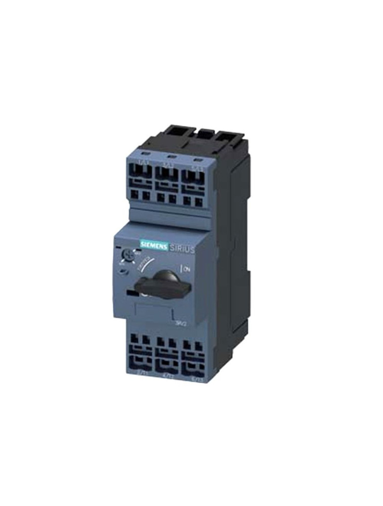
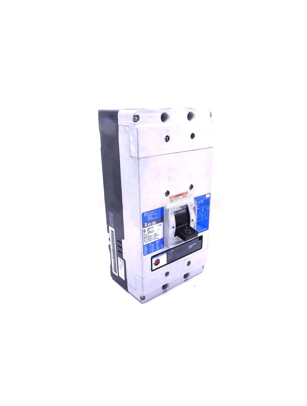
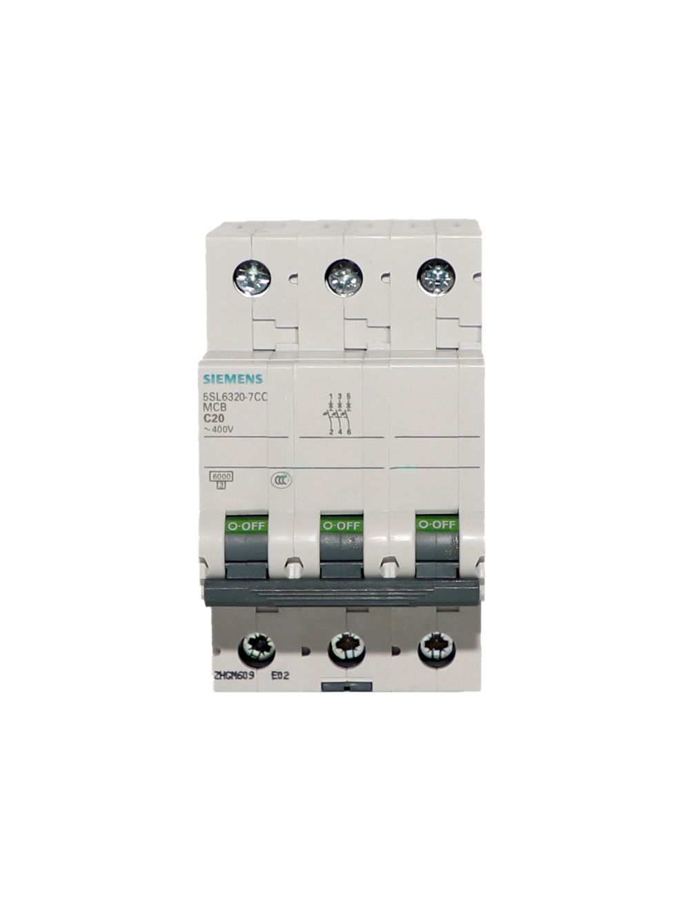
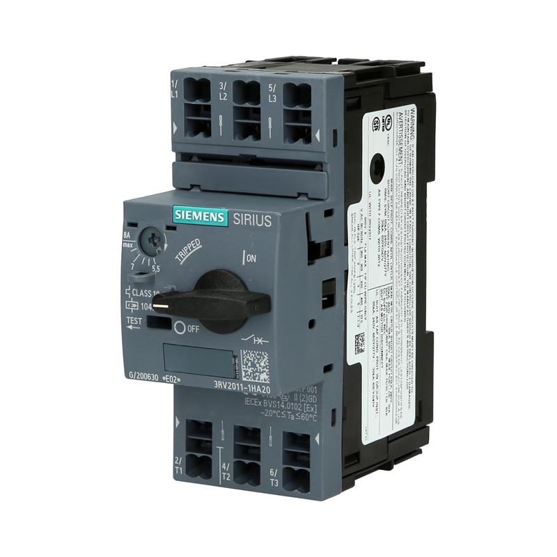
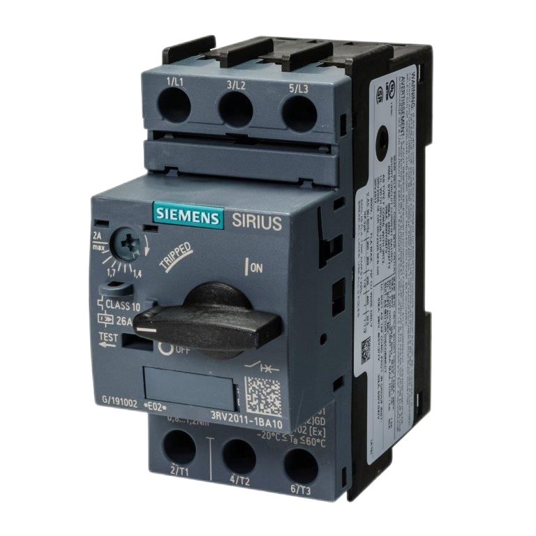
Siemens Circuit Breaker 3RV2011-0CA40
$ 191 .20
(5) 1
Reviews
Quantity
MOQ : 2
Payment Methods


- Specifications
- Q&A
- Reviews
Parameter
| Type | 3RV2 |
| Breaker Type | Motor Protection Circuit Breakers |
| Rated current | 0.25 |
| Number of Poles | 4 pole |
| Setting range for thermal overload releases | 0.18...0.25 A |
The Siemens Circuit Breaker is high quality!
Circuit breaker size S00 for motor protection, CLASS 10 A-release
0.18...0.25 A N-release 3.3 A ring cable lug connection Standard
switching capacity
product brand name SIRIUS
product designation Circuit breaker
design of the product For motor protection
product type designation 3RV2
General technical data
size of the circuit-breaker S00
size of contactor can be combined company-specific S00, S0
product extension
auxiliary switch Yes
power loss W for rated value of the current
at AC in hot operating state 5.5 W
at AC in hot operating state per pole 1.8 W
insulation voltage with degree of pollution 3 at AC
rated value
690 V
surge voltage resistance rated value 6 kV
maximum permissible voltage for safe isolation
in networks with grounded star point between
main and auxiliary circuit
400 V
in networks with grounded star point between
main and auxiliary circuit
400 V
protection class IP
on the front IP00
of the terminal IP00
shock resistance
acc. to IEC 60068-2-27 25g / 11 ms
mechanical service life (switching cycles)
of the main contacts typical 100 000
of auxiliary contacts typical 100 000
electrical endurance (switching cycles)
typical 100 000
type of protection according to ATEX directive
2014/34/EU
Ex II (2) GD
certificate of suitability according to ATEX directive
2014/34/EU
DMT 02 ATEX F 001
reference code acc. to DIN EN 81346-2 Q
Ambient conditions
installation altitude at height above sea level
maximum
2 000 m
ambient temperature
during operation -20 ... +60 degrees centigrade
during storage -50 ... +80 degrees centigrade
during transport -50 ... +80 degrees centigrade
temperature compensation -20 ... +60 degrees centigrade
relative humidity during operation 10 ... 95 %
Main circuit
number of poles for main current circuit 3
adjustable pick-up value current of the currentdependent
overload release
0.18 ... 0.25 A
operating voltage
rated value 690 V
at AC-3 rated value maximum 690 V
operating frequency rated value 50 ... 60 Hz
operating current rated value 0.25 A
operating current
at AC-3
at 400 V rated value 0.25 A
operating power
at AC-3
at 230 V rated value 40 W
at 400 V rated value 60 W
at 500 V rated value 90 W
at 690 V rated value 120 W
operating frequency
at AC-3 maximum 15 1/h
Auxiliary circuit
number of NC contacts for auxiliary contacts 0
number of NO contacts for auxiliary contacts 0
number of CO contacts
for auxiliary contacts 0
Protective and monitoring functions
product function
ground fault detection No
phase failure detection Yes
trip class CLASS 10
design of the overload release thermal
operational short-circuit current breaking capacity
(Ics) at AC
at 240 V rated value 100 kA
at 400 V rated value 100 kA
at 500 V rated value 100 kA
at 690 V rated value 100 kA
maximum short-circuit current breaking capacity (Icu)
at AC at 240 V rated value 100 kA
at AC at 400 V rated value 100 kA
at AC at 500 V rated value 100 kA
at AC at 690 V rated value 100 kA
response value current
of instantaneous short-circuit trip unit 3.3 A
UL/CSA ratings
full-load current (FLA) for three-phase AC motor
at 480 V rated value 0.25 A
at 600 V rated value 0.25 A
Short-circuit protection
product function short circuit protection Yes
design of the short-circuit trip magnetic
Installation/ mounting/ dimensions
mounting position any
mounting type screw and snap-on mounting onto 35 mm standard mounting rail
according to DIN EN 60715
height 97 mm
width 45 mm
depth 97 mm
required spacing
for grounded parts at 400 V
downwards 30 mm
upwards 30 mm
at the side 9 mm
for live parts at 400 V
downwards 30 mm
upwards 30 mm
at the side 9 mm
for grounded parts at 500 V
downwards 30 mm
upwards 30 mm
at the side 9 mm
for live parts at 500 V
downwards 30 mm
upwards 30 mm
at the side 9 mm
for grounded parts at 690 V
downwards 50 mm
upwards 50 mm
backwards 0 mm
at the side 30 mm
forwards 0 mm
for live parts at 690 V
downwards 50 mm
upwards 50 mm
backwards 0 mm
at the side 30 mm
forwards 0 mm
Connections/ Terminals
product function
removable terminal for auxiliary and control
circuit
No
type of electrical connection
for main current circuit Ring cable lug connection
for auxiliary and control circuit ring cable connection
arrangement of electrical connectors for main current
circuit
Top and bottom
tightening torque
for main contacts for ring cable lug 0.8 ... 1.2 N.m
for auxiliary contacts for ring cable lug 1.2 ... 0.8 N.m
outer diameter of the usable ring cable lug maximum 7.5 mm
design of screwdriver shaft Diameter 5 to 6 mm
size of the screwdriver tip Size 2 and Pozidriv 2
design of the thread of the connection screw
for main contacts M3
of the auxiliary and control contacts M3
Safety related data
B10 value
with high demand rate acc. to SN 31920 5 000
proportion of dangerous failures
with low demand rate acc. to SN 31920 50 %
with high demand rate acc. to SN 31920 50 %
failure rate FIT
with low demand rate acc. to SN 31920 50 FIT
T1 value for proof test interval or service life acc. to
IEC 61508
10 y
display version
for switching status Handle
 Question has been sent successfully


/Eaton-Contactor-DILK20-11(380V50-60HZ).jpg)

-(55D23L-KR)/GS-Battery-6-QW-60(450)-(55D23L-KR).jpg)