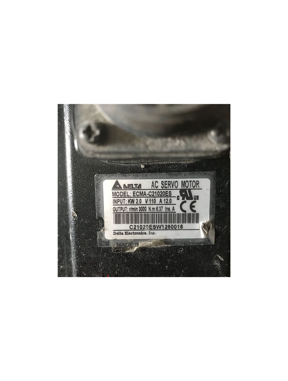
Figure 1: Servo motor and servo drive.
Servo motors play an important role in the field of automation and are usually used to drive components that require more precise speed or position control in projects. Designers of automation equipment often need to face various motor selection problems with different needs. This article first introduces the selection steps and principles of servo motors, and then explains how to select servo motors for automation equipment design.
1. Servo Motor Selection Steps and Selection Principles
(1) Clarify the movement condition requirements of the load mechanism, that is, the speed of acceleration/deceleration, movement speed, weight of the mechanism, movement mode of the mechanism, etc.
(2) Select an appropriate load inertia calculation formula to calculate the load inertia of the mechanism based on the operating conditions.
(3) Select the appropriate servo motor specifications based on the load inertia and servo motor inertia.
(4) Combine the selected servo motor inertia and load inertia to calculate the acceleration torque and deceleration torque.
(5) Calculate the load torque based on the load weight, configuration, friction coefficient, and operating efficiency.
(6) The maximum output torque of the selected servo motor must be greater than the acceleration torque + load torque; if it does not meet the conditions, other models must be selected for calculation and verification until it meets the requirements.
(7) Calculate the continuous instantaneous torque based on the load torque, acceleration torque, deceleration torque and holding torque.
(8) The rated torque of the selected servo motor must be greater than the continuous instantaneous torque. If the conditions are not met, other models must be selected for calculation and verification until the requirements are met.
(9) Complete the selection.

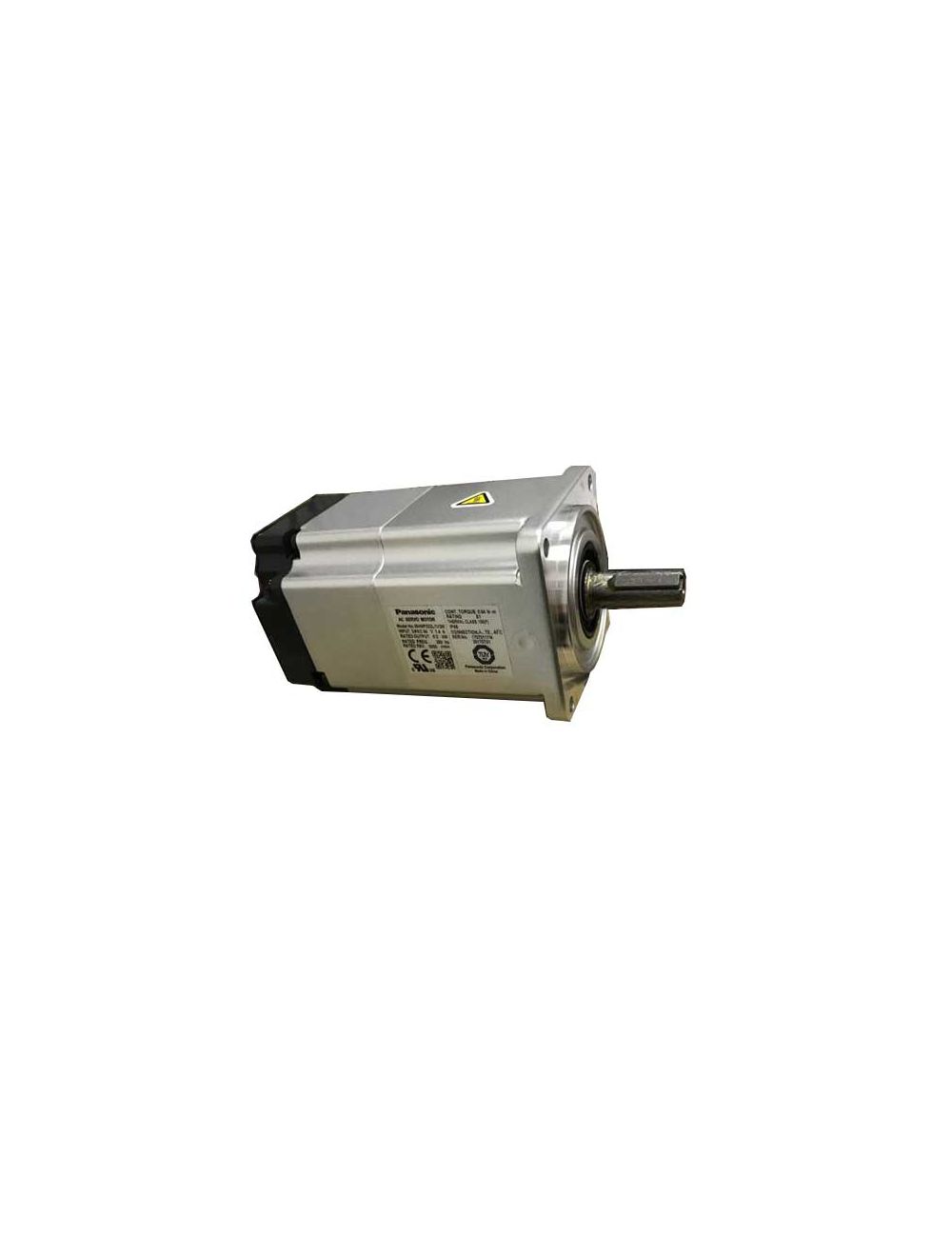
Figure 2: Servo motor and related equipment.
2. How to Choose Servo Motors for Automation Equipment
2.1 Application Scenarios
Control motors in the field of automation can be divided into servo motors, stepper motors, inverter motors, etc. For components that require more precise speed or position control, servo motor drives will be chosen.
The control method of frequency converter + inverter motor is a control method that changes the motor speed by changing the power frequency of the input motor, generally only used for motor speed control.
Servo motor compared with stepper motor:
a) The servo motor uses closed-loop control, and the stepper motor uses open-loop control.
b) The servo motor uses a rotary encoder for measurement accuracy, and the stepper motor uses a step angle for accuracy control. At the ordinary product level, the accuracy of the former can reach hundreds of times that of the latter.
c) Their control methods are similar (pulse or direction signal).
2.2 Power Supply
Servo motors can be divided into AC servo motors and DC servo motors based on the power supply.
For general automation equipment, Party A will provide a standard 380V industrial power supply. At this time, just select the servo motor corresponding to the power supply, avoiding the need to convert the power supply type. However, some equipment, such as the pallet shuttle and AGV trolley in three-dimensional warehouses, mostly uses their own DC power supply because of their mobile nature, so DC servo motors are generally used.

Figure 3: Warehouse with pallet shuttles.
2.3 Brake
According to the design of the action mechanism, consider whether there will be a reversal tendency of the motor during a power outage or a static state. If there is a tendency to reverse, you need to choose a servo motor with a holding brake.
2.4 Selection and Calculation
Before selection and calculation, the first thing to determine is the position and speed requirements of the end of the mechanism, and then determine the transmission mechanism. At this point you can select the servo system and corresponding reducer.
During the selection process, the following parameters are mainly considered:
1. Power and Speed
Calculate the required power and speed of the motor based on the structural form and speed and acceleration requirements of the final load. It is worth noting that usually the reduction ratio of the reducer needs to be selected based on the speed of the selected motor.
In the actual selection process, for example, if the load moves horizontally, it is often impossible to clearly calculate the torque using the formula P=T*N/9549 due to the uncertainty of the friction coefficient and wind load coefficient of each transmission mechanism. (P is power, unit: Watt (W); T is torque, unit: N.m; N is motor speed, unit: rad/s.) In practice, it is also found that the maximum power required when using a servo motor is often at the acceleration and deceleration stage.
Therefore, the required power of the motor and the reduction ratio of the reducer can be quantitatively calculated through T=F*R=m*a*R (F represents the force acting on the object; m: load mass; a: load acceleration; R : load rotation radius).
There are a few points to note:
a) The power margin coefficient of the motor;
b) Consider the transmission efficiency of the mechanism;
c) Whether the input and output torque of the reducer meet the standards and have a certain safety factor;
d) Whether there is a possibility of increasing the speed in the later period.
Note: When the load is running vertically, take the acceleration due to gravity into consideration.

Figure 4: Servo motor worm gear reducer.
2. Inertia Matching
To achieve high-precision control of the load, it is necessary to consider whether the motor and the inertia of the system match.
The principle of inertia matching: consider that the system inertia is converted to the motor shaft, and the inertia ratio to the motor is no more than 10 (Siemens); the smaller the ratio, the better the control stability, but a larger motor is required, which is less cost-effective.
3. Accuracy Requirements
Calculate whether the control accuracy of the motor can meet the load requirements after changes in the reducer and transmission mechanism. The reducer or some transmission mechanisms have a certain back clearance, which needs to be considered.
4. Control Matching
This aspect mainly involves communicating with the electrical designer to confirm, such as whether the communication method of the servo controller matches the PLC, the type of encoder and whether data needs to be extracted, etc.

Figure 5: Servo control system schematic diagram.
2.5 Environmental Conditions
Environmental conditions are another important consideration when selecting a servo motor. Different applications may require motors to operate under different conditions of temperature, humidity and pressure. Some applications may require dust-, water- or corrosion-proof motors. Therefore, when selecting a servo motor, you need to consider the motor's environmental sealing and durability. This helps ensure the motor maintains high performance and extends its life under harsh operating conditions.
2.6 Brand
Currently, there are many brands of servo motors on the market, and their performance varies widely. Some commonly used servo motor brands:
European and American: Siemens, ABB, Lenz, etc.;
Japanese: Panasonic, Mitsubishi, Yaskawa, etc.
Conclusion
Servo motors play a key role in modern engineering and automation systems, and the correct selection of motor type and specification is crucial to the success of your project. As a trusted supplier, O&Kmarts can provide you with various servo motors from different brands. If you are interested, please feel free to contact us.

100-38/MINAMOTO-Water-Pump-GD(2)100-38.jpg)