


Compressor starting circuit diagram
[Introduction] Compressor startup circuit diagram. Refrigerators, air conditioners and other appliances, the compressor is driven by a single-phase induction motor. When starting, the induction motor must overcome both its own inertia and high-pressure refrigeration Compressor starting circuit diagram The compressors of electric appliances such as refrigerators and air conditioners are driven by single-phase induction motors. When starting, the induction motor must overcome both its own inertia and the reaction force of the high-pressure refrigerant. Therefore, the motor needs a large starting current and torque, and when the motor is operating normally, the above torque will drop significantly. To this end, a compressor start-up circuit needs to be added to provide the torque required for the motor to start. This circuit should be automatically disconnected after entering normal operation. The compressor start-up circuit using PTC thermistor is superior to the past heavy-duty start-up circuit. It has the characteristics of no contact, low noise, high reliability and long life. Taking the refrigerator compressor as an example, the commonly used compressor starting circuit is introduced here.

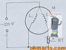
2.18.1 Principle circuit Figure 2.18.1 is the starting circuit of the split-phase compressor. In the figure, L1 is the main winding of the motor M; L2 is the auxiliary winding, which forms the starting circuit with RT (PTC thermistor). When the power is turned on, RT is in a cold state, and its resistance value R is negligible compared to the impedance XL2 of L2, thereby ensuring sufficient starting current. With the continuation of the power-on time, the resistance value of RT rises rapidly due to self-heating. Its resistance value is much greater than XL2, and the startup circuit is similar to an open circuit. This circuit is often used in reciprocating compressors. Figure 2.18.1 Starting circuit of split-phase compressor Figure 2.18.2 is the starting circuit of the capacitive compressor. This circuit is basically the same as the split-phase circuit, except that a capacitor C is connected in series with the auxiliary winding. Its function is to increase the phase difference of the current in the main and auxiliary windings, thereby further increasing the starting torque of the motor. In this way, even when the power supply voltage is low, the motor can be started and enter the normal operation state. This circuit is commonly used in rotary compressors. Figure 2.18.2 Starting circuit of capacitive compressor 2.18.2 Selection of main components In order to ensure that the compressor has good starting characteristics and overload capacity, it is very important to choose a PTC thermistor reasonably. ①, room temperature resistance generally choose 22~100Ω. ② Curie temperature depends on the temperature rise of the compressor, generally 30~50℃ higher than it, usually 100~140℃. ③ The residual current is usually 5~10mA. ④, recovery characteristics Recovery time is less than 90s. ⑤ Maximum voltage 500~800V.
