


Because the output signal of the sensor is very small, it is usually only a few millivolts. In order to improve the anti-interference ability of the instrument, the zero potential in the input circuit must be grounded and take the earth potential as itself which is the sufficient condition for the grounding of the sensor. The following describes how to properly ground the electromagnetic flowmeter under three different installation conditions.
1. Grounding of Electromagnetic Flowmeter When It is Installed on Metal Pipeline
Connect the grounding wire of the sensor to the pipe flanges on both sides according to the requirements of the manufacturer to form a reliable grounding circuit, as shown in the figure.
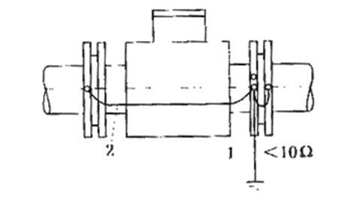
Figure 1: Installation of sensor on metal pipe.
1.Grounding; 2. Grounding wire(4-16mm2 Copper wire)
2. Grounding of Electromagnetic Flowmeter When It is Installed on Insulated Pipe
When the sensor is installed on plastic pipe or metal pipe with insulating coating, lining and paint layer on the inner wall, metal short pipe or grounding ring must be installed at both ends. Then connect with a wire and "connect" with the fluid, as shown in Figure 2.
If the measured fluid is highly corrosive and it is difficult to install the metal short pipe and grounding ring in terms of materials, we can punch holes on the insulated pipes at both ends of the sensor and install the grounding electrode. The grounding electrode is made of corrosion-resistant alloy material. We should connect it with the grounding screw of the sensor with a wire.

Figure 2: Installation of the sensor on the insulated pipe.
1.Grounding; 2. Grounding wire(4-16mm2 Copper wire)3. Grounding ring
3. Grounding of Electromagnetic Flowmeter When It is Installed in The Pipeline With Strong Stray Current
When the stray current in the pipeline is very strong measuring the electrolyte flow in the pipeline near the electrolytic cell, the stray current will cause serious interference. In this case, the installation and grounding methods shown in Figure 3 can be adopted.

Figure 3: Installation of the sensor in the pipeline with strong stray current.
1.Grounding; 2. Grounding wire(4-16mm2 Copper wire)3. Grounding ring
4.Insulated pipe; 5. Connecting wire(4-16mm2 Copper wire)
Connect a insulated pipe to both ends of the sensor and install a grounding ring between the sensor and the insulated pipe. Like the general installation and grounding methods, the grounding ring and the flange of the sensor are connected with a well grounded grounding rod. The process pipes on both sides of the insulated pipe are short circuited with connecting wires. In this way, the leakage current is mainly shunted and short circuited from the connecting copper wire, and the interference introduced from the measured liquid into the sensor signal circuit is greatly reduced.
When the installation environment has strong influence of leakage current and electric field, the sensor must be grounded. The ground wire is connected to the grounding rod buried in a certain depth (the grounding rod is buried in the wet soil with a depth of more than 1m) with multi strand copper wires with a total cross-sectional area of no less than 4-16mm2.
4. Summary
The contents above emphasize the importance and implementation method of grounding. Compared with some interference on site, the signal of electromagnetic flowmeter is too weak. So, grounding is relatively important, especially in the water supply industry. The grounding effect directly determines the use of electromagnetic flowmeter!
Related Info
What is a flowmeterWhat is a thermal mass flowmeter
How to unclog expansion valve
