
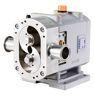
Lobe Pump
Cam pump technology began in Germany in the 1990s. Its technical characteristics are perfect, and its rotor is fully covered by special rubber with three helical blades. It has high vacuum degree and super wear resistance and corrosion resistance. It is widely used in military industry, oil exploration and other fields. Domestically produced cam pumps are mainly metal cam pumps. This technology is mainly used in the fields of food and chemical industry. The clearance between the cam rotor and the pump body causes particles to be easily stuck in the pump, and the overall efficiency is not high.
Working principle
The lobe pump relies on two synchronous and counter-rotating rotors to generate suction (vacuum) at the inlet during the rotation process, thereby sucking the material to be transported. The two rotors divide the rotor chamber into several small spaces, and they operate in sequence, and the medium is transported to the discharge port. In such a cycle, the medium (material) is continuously conveyed out.
Why choose the Lobe Pumps?
Lobe pumps are chosen due to the low speeds they can be operated at between 20-1200rpm ensuring liquids are handled in a gentle slow-motion preventing their consistency from being changed. They handle between 1cst and 55,000 CST, and produce flows up to 300M³H, while handling liquids up to 150°C.
Lobes can be manufactured from Stainless Steel AISI316 which are hygienic rated and of sanitary design, but can also be rubber for use in industrial applications. Rubber Lobed pumps are self priming up to 6M as the rubber parts create an airtight seal, which is not possible with Metallic lobes. Metallic & Rubber lobes can be in tri (Y) or twin (I) lobed design, with all materials being able to operate in reverse.
The pump is sealed via a mechanical seal, double mechanical seal, packed gland or lipped seal. Heating Jackets can be fitted to ensure stable liquid temperature, and a bypass valve can be fitted on the front cover or externally to help prevent overpressurisation. Lobe pumps can be operated in both directions but a relief valve will only operate in one direction.
Units can be made suitable for dry running providing a lubricated seal system to the shaft seal preventing overheating.
This design of pump are easy to maintain given the front casing design. The casing can be opened easily through the undoing of four bolts, and inner parts and seals can be replaced within minutes. A seperate chamber between the gearbox and pump housing ensures should a seal failure occur in either the pump or gearbox that the two liquids do not interact.
Pump heads can contain wear plates to prevent the accelerated wear of the pump casing during the handling of solid laden sludges, or hard particles. This ensures cost effective maintenance of the unit throughout its life. Applications include the handling of viscous liquids, which can contain solids up to 50mm, and gas slugs.
Advantages of Lobe Pump
The advantages of lobe pumps are as follows:
Lobe pumps can handle solids, slurries, pastes and many liquid.
No metal-to-metal contact.Superior CIP(Cleaning in Place) /SIP(Sterilization in Place) capabilities.
Long-term dry run (with lubrication to seals).Non-pulsating discharge.
Lobe pump use precautions
1. During the installation of the Lobe pump, the position space required for future maintenance should be fully considered, and the anchor screw of the Lobe pump should be adjusted to make its whole in a horizontal state. In the process of connecting the pipeline, attention should be paid to the link of the feed pipeline. The connection of the feed pipe must be kept horizontal to prevent residual air or gas from being left in the pipe and affecting the normal operation of the equipment.
2. For high viscosity materials should be used high feeding method, in order to improve the feeding pressure of the feeding pipeline.
3. Please arrange the inlet pipe in strict accordance with the import and export mark on the factory equipment, and do not allow the reverse connection. If the user has special requirements for the inlet, please explain when ordering.
4. Please strictly in accordance with the steering mark on the pump housing wiring, do not allow reverse rotation.
Papson rotor pump, also known as Lobe pump, is a positive displacement pump family of a very important role. The pump structure is compact, covers an area of small, widely used in a variety of industry conditions, for conveying high solid content, high wear, high viscosity medium. In addition, the rotor pump has a very high self-priming capacity, positive and reversible transmission characteristics, the flow size is proportional to the speed of the linear characteristics, in many occasions has unique application advantages. Rotor material type and pump installation form is very diverse, can meet the needs of a variety of working conditions.
Lobe pump in principle only in the basic selection of working pressure and total flow, purchase order, viscosity, temperature, ph, solid water content and other actual operating standards, as far as possible to reduce the operation of more than the standard in the work. Always check the barometer, valve and overcurrent protection equipment when the increase of raw material viscosity, total flow rate and working pressure can easily cause motor load.
Pump containing heat insulation equipment should be used to warm the boiling water before operation, and then run after pump temperature rises to the whole process of conveyor. You should turn off the pump before turning off the boiling water. The cooling circulation water machine sealing equipment must be opened before operation, and then the pump, and often observe whether the cooling circulation water is normal. No cooling circulating water operation time.
After installing the new pump, the filter device should be cleaned, and the filter device should be cleaned in a month, so that the pump can not run normally. When the conveyor condensates low viscosity materials, the pump should be stopped before the material dilution pump to avoid condensation in the residual pump, if not necessary, the low viscosity materials should be cleaned with the cleaning liquid by the pump circulation system for 5-10 minutes.
After the water is cooled, the condenser material thickens. After surgery, clean the inner wall with a cleaning solution for 5-10 minutes. If necessary, change the cleaning solution several times, and increase the cleaning time. The slag and hard particulate matter in the drainage pipe must be eliminated in the newly installed drainage pipe to prevent it from entering the pump cavity and damaging the stator, pump shell, spindle bearing, machine seal, etc. Regularly maintain all connections and tighten screws, if any, tighten immediately. Always check the gearbox oil mirror. If the oil surface is visible, it must be fed. The drip should be more than half of the oil mirror.
 Ball Valve
