


This article continues to introduce the function and working principle of other related components of the refrigeration system, including pressure controllers, oil separators, filter driers, etc.
1. Pressure Controller

Figure 1: The installation position diagram of the dual pressure controller in the refrigeration system.
What happens if the solenoid valve blocks the flow of refrigerant to the evaporator while the compressor is still running? Intake pressure drops. At this time we need to stop the compressor in order to control the system pressure and prevent the inlet pressure from dropping below the nominal.
In addition, if the condensing pressure rises too high due to a dirty condenser or fan failure, the compressor must also be stopped to prevent it from exceeding its operating range.
There are two common pressure controls:
Single pressure control: Divided into low pressure controller and high pressure controller.

Figure 2: Danfoss single pressure control.
Dual pressure control: One controller has both low-pressure control and high-pressure control.

Figure 3: Emerson dual pressure control.
1.1 Principle and Function of Pressure Controller
The pressure controller can control and protect the system by preventing the inlet pressure (evaporator pressure) from being too low or the discharge pressure (condenser pressure) from being too high.
The pressure controller has two main functions:
1. Protection (or safety) function: limit the pressure, and cut off the power supply when the system pressure is too low or too high.
2. Control function: control compression cycle, and condenser fan cycling.
High and Low Pressure Protection of Refrigeration Compressor
Refrigeration compressors often require protection against high condensing pressure or low inlet pressure.
This is achieved by using two single pressure switches or one dual pressure switch. Switches come in a variety of electrical contact types. What you see here is a simple type, and high and low pressure switches are combined in one housing.
If the pressure reaches the HIGH set value, the switch will open contacts A and C. The switch will also open contacts A and C if the pressure falls below the LOW set value.

Figure 4: Working principle diagram of the pressure control of the refrigeration system.
2. Oil Separator
The hot refrigerant gas discharged from the compressor will carry away the oil in the compressor. Sometimes the amount of oil taken away is too large, and it no longer returns to the compressor.
In order to prevent this situation, an oil separator is used to separate the oil from the refrigerant and return it to the compressor.
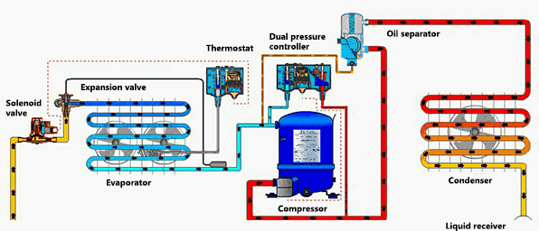
Figure 5: Installation position diagram of the pressure controller in the refrigeration system.
2.1 Function of Oil Separator
The role of the oil separator:
1. The oil separator separates the oil in the hot refrigerant gas, and returns it to the oil sump of the compressor through the built-in control device.
2. The oil separator can prevent oil shortage and protect the compressor.
3. The oil separator can prevent oil from accumulating to reduce compressor efficiency, so it has a protective effect on the refrigeration system.
2.2 Working Principle of Oil Separator
The oil separator collects the oil in the refrigerant to the bottom of the separator. As the oil level rises, the float opens the needle valve, allowing oil to return to the compressor sump. As the oil level drops, the float moves down and closes the needle valve.

Figure 6: Working principle diagram of oil separator.
3. Filter Drier
Other foreign objects such as water, metal oxides, and dirt may be present in the refrigeration system, which can reduce the efficiency of the system or cause the system to stop working. So a filter drier is needed to remove these foreign substances from the refrigerant, ensuring the system works more efficiently.
The function of filter drier:
1.The filter drier prevents the refrigeration system from sucking harmful substances.
2.The filter drier removes moisture from the refrigerant to prevent ice forming on the orifice of the expansion valve.
3.It also removes other solid contaminants, corrosion and acids to minimize chemical reactions in the system.

Figure 7: Cutaway view of filter drier.
4. Sight Glass
The function of the sight glass is to observe the liquid level of the refrigerant and detect whether there is water vapor at the rear end of the filter drier in the system.
1. The sight glass can detect the water vapor in the refrigerant, and it is usually installed at the back end of the filter drier.
2. The color indicator in the sight glass can display the water vapor content.
Green - The refrigerant does not contain dangerous water vapor.
Yellow - There is too much water vapor in the liquid line ahead of the expansion valve.
If bubbles are seen through the sight glass, the following conditions exist.
1. The pressure drop across the filter drier is too high, possibly caused by clog.
2. Insufficient subcooling.
3. Insufficient refrigerant in the whole system.

Figure 8: A sight glass.
5. Globe Valve / Ball Valve
How to isolate a component/controller when doing system diagnostics? The refrigeration circuit must be shut off before isolating the components. Globe valves or ball valves are used for this purpose in the refrigeration system.
The function of globe valve/ball valve:
1.The function of the globe valve/ball valve is to close the refrigeration circuit so that the system can be diagnosed and parts can be replaced.
2.They isolate refrigeration system components for servicing, diagnostics and measurements.

Figure 9: A ball valve.
6. Pressure Regulator
The function of a pressure regulator is to control the pressure level in the system, allowing the system to work more efficiently under various conditions. There are three types of pressure regulators.
Figure 10: Installation position diagram of evaporator pressure regulator in refrigeration system.
6.1 Evaporator Pressure Regulator
The first is the evaporator pressure regulator. It controls the evaporating pressure at a predetermined level, even when ambient/system conditions change.
The primary function of the evaporating pressure regulator is to maintain a constant pressure inside the evaporator; therefore, it opens and closes depending on the load on the evaporator.
Changes in pressure at the outlet of the pressure regulator will not affect its opening because the regulator has a balanced bellows (bellows and valve seat are equal in area).
The evaporator pressure regulator has a pressure gauge connection for setting the desired evaporating pressure.

Figure 11: Working principle diagram of evaporator pressure regulator.
6.2 Condensing Pressure Regulator
Condensing pressure regulators for air-cooled condensers are usually used together with differential pressure valves to adjust the condenser pressure.
When the condenser pressure valve closes, creating a pressure drop greater than 1.4 bar, the differential pressure valve will begin to open to maintain a sufficiently high liquid receiver pressure. The pressure controller controls the on/off of the condenser fan.
Working Principle and Process of Condensing Pressure Regulator
The condenser pressure control system consists of a pressure regulator and a differential pressure valve.
Condenser pressure regulators control the condenser pressure so that the condensing pressure is maintained at a certain level - even when the ambient air temperature is low. This is to maintain the necessary (minimum) differential pressure for the thermal expansion valve.

Figure 12: Working principle diagram of condensing pressure regulator.
In areas where the ambient temperature varies drastically, this system can solve many condenser control problems because it dampens pressure changes and thus prevents problems.
6.3 Differential Pressure Regulator Valve
The differential pressure valve is used in the hot gas line between the exhaust line and the liquid receiver to maintain the pressure of the liquid receiver at a certain level.
With internal spring force, the valve starts to open at a differential pressure of 1.4 bar and fully opens at 3 bar. The greater the pressure difference of the valve, the greater its opening degree.
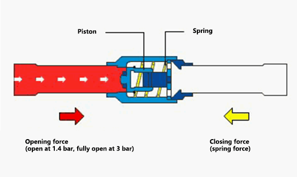
Figure 13: Working principle diagram of differential pressure valve.
Working Principle of Differential Pressure Valve
Now let's look at how the condensing pressure control system works.
If the ambient temperature drops, the condenser pressure will also drop. Then:
1. The pressure controller turns off the fan, allowing the condenser pressure to rise gradually.
2. If this is not enough, the condenser pressure regulator starts to close.
As the condenser pressure begins to rise, the liquid receiver pressure will likely drop as the liquid in it flows to the evaporator.
3. The condenser pressure regulator is nearly closed or fully closed, the pressure difference between the hot gas discharge line and the liquid receiver reaches 1.4 bar, and the differential pressure valve (NRD) starts to open to increase the pressure of the liquid receiver.

Figure 14: Working principle diagram of condensing pressure control system.
7. Conclusion
The main purpose of the automatic control of the refrigeration system is to optimize its performance, and the methods include:
• Use an expansion valve to control liquid refrigerant injection into the evaporator.
• Use a liquid receiver to compensate for liquid level changes of condenser.
• Control the temperature of the cold room/medium with a thermostat.
• Liquid flow to the evaporator is controlled by a solenoid valve.
• Protect the system with safety devices against low or high pressure.
• Use an oil separator to minimize oil entering the system.
• Use a filter drier to prevent damage from moisture and contaminants in the system.
• Use the sight glass to prevent overcharging or undercharging of the system while checking the refrigerant condition.
• Minimize repair time with globe or ball valves.
• Maintain system temperature and pressure on the low and high pressure sides with pressure regulators.
• Improve system efficiency with expansion valves, oil separators and condensing pressure controllers.
Equipment composition of a typical ammonia vapor compression refrigeration system (ammonia pump liquid supply)

Figure 15: Ammonia refrigeration system components.
Related Info
15 Refrigeration System Components Structure, Function, Working Principle Diagram (1)Which Brand of Refrigerator is Better (6 Top Refrigerator Brands 2023)
How to Quiet a Noisy Refrigerator (11 Ways)
How to Replace Refrigerator Compressor
How to Tell if Refrigerator Compressor is Bad
