


Combined air conditioning installation operation and daily maintenance
installation:
Unit installation and construction,
1. Preparation before installation
(1) Familiarize with and review all relevant drawings and documents, and check whether the unit placement position and basic dimensions meet the requirements.
(2) Confirm that the equipment model specifications and random accessories meet the order contract, and the physical quality is qualified.
(3) Prepare lifting and handling equipment, prepare installation tools and other necessary materials.
(4) Coordinate with the installation progress of civil engineering, water, electricity and air duct projects to facilitate the smooth completion of the entire system.
2. Hoisting and handling
(1) Please do not open the outer packaging of the unit before the unit reaches the final installation point. After arriving at the final installation starting point, first unpack the unit to check whether there is any damage during transportation. If there is any damage, you should confirm it in time and file a claim with the transporter, and check whether the number of accessories is correct according to the "Product Packing List".
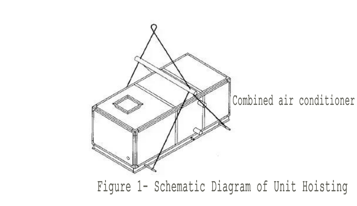
(2) In order to prevent damage to the unit cabinet during the lifting and installation process, when lifting with ropes, the ropes should be placed on the base of the unit. (See Figure 1-Schematic diagram of unit hoisting)
(3) When using rollers for transportation, at least three rollers with a length greater than the width of the unit should be used.
(4) During hoisting and transportation, it must be handled with care and safety.
3. The unit is installed in place
(1) The quality of the air conditioning unit installation has a great impact on the operation and maintenance of the equipment.
(2) The unit should be placed on a suitable foundation. The following two forms are recommended for the installation foundation. The foundation should be leveled and have sufficient support strength. (See Figure 2-Schematic diagram of unit installation foundation)

Figure 2-Schematic diagram of unit installation foundation
(3) Sufficient maintenance space should be left around the foundation of the unit (see Figure 3-Schematic Diagram of Maintenance Space) for daily inspection and regular maintenance of the unit.
(4) Unit installation should place all functional section boxes on the foundation in order according to the drawings. For occasions with high seismic requirements, damping pads should be placed between the unit and the foundation. The damping pads are generally natural rubber sheets. The thickness is more than 10mm.
(5) If the unit is hoisted from the ceiling, the platform must be hoisted. The size of the platform must be larger than the unit and the maintenance space should be considered. The level of the platform should be adjusted and the unit should be installed smoothly, and it must not bear the weight of external water pipes and air pipes.
(6) The connection between the sections of the unit is connected by bolts. The polyethylene high-foamed plastic board is first pasted between the two sections. The installation is shown in Figure 4-the installation diagram of the connection between the sections. The bolt spacing is 200mm, and then the unit The base is connected by bolts.

Figure 4-Schematic diagram of installation between segments
Figure 4-Schematic diagram of installation between segments

Figure 3-Schematic diagram of maintenance space
)
(7) When connecting the vertical unit sections, the distance between the frame and the unit base connecting self-tapping screws M6×20 is 200mm. When the unit leaves the factory, the unit base has been connected to the upper frame. Only use self-tapping screws M6× when installing. 20 Just connect the lower frame. (See Figure 5-Schematic diagram of connection between sections of vertical unit)
(8) When there is a panel connection between the positive pressure sections (generally the fan section and other functional sections), the spacing of the self-tapping screws M6×20 of the connecting plate between the sections is 200mm. (For details, please refer to Figure 6-Diagram of Connection Between Positive Pressure Sections)

Figure 5-Schematic diagram of connection between vertical units

Figure 6-Schematic diagram of connection between positive pressure sections
9) If you need to install or operate on the top of the unit, you must stand on the frame bar, not on the panel.
(10) Use angle iron brackets and flanges for dry steam humidifier to fix the humidifier body and nozzle on the panel of the humidification section respectively. See

As shown in Figure 7-the installation diagram of the steam humidifier, the steam injection direction of the humidifier is reverse air flow, and a steam trap is installed at the steam outlet.

4. Air duct installation and connection
Please select the appropriate duct according to the air volume and static pressure of the unit. Each air duct should be insulated, and the insulation material should include a moisture-proof layer to prevent moisture absorption.
(1) Install air volume regulating valves on the inlet and outlet ducts of the unit to facilitate system debugging and make the air volume and pressure appropriate. The inlet and outlet of the unit and the inlet and outlet pipes should use soft connections.
(2) The unit shall not bear the weight of the external pipes, and all air inlet and outlet pipes shall be supported and fixed.
(3) The space required for unit maintenance must be considered when installing pipelines.
Note: Before connecting the air outlet of the unit to the curved pipe, the air outlet pipe should maintain a straight pipe that is at least twice the length of the air outlet, otherwise it will cause additional air pressure loss.
5. Water pipe installation and connection
The installation of all piping systems must comply with local regulations.
(1) The maximum operating pressure of the surface cooler and hot water heater should not exceed 1.6MPa, and the inlet and outlet pipes should be connected by pipe threads or flanges. The pipe threads should be wrapped with raw material tape. Out". (See Figure 8-Installation diagram of coil inlet and outlet pipes)
heater, surface cooler (single layer)
heater, surface cooler (double layer)
Figure 8-Schematic diagram of installation of coiled water inlet and outlet pipes
(2) The maximum operating pressure of the steam heater does not exceed 1.4MPa. The inlet and outlet steam pipes are connected by pipe threads or flanges. The steam inlet is "top inlet and bottom outlet", and a steam trap should be installed at the outlet. (See Figure 9-Installation diagram of steam heater inlet and outlet pipes)
Steam heater (single layer)
steam heater (double layer)

Figure 9-Installation diagram of steam heater inlet and outlet pipes
(3) The inlet and outlet pipes of the unit should be equipped with regulating valves (except the condensate drain pipe) to adjust the flow rate and cut off the water source during maintenance. The inlet and outlet pipes of the unit shall be insulated. A U-shaped water seal must be installed on each condensate drain pipe. For installation, see the schematic diagram of the U-shaped water seal installation in Figure 2.
(4) Pressure gauges and thermometers should be installed in the inlet and outlet water pipes of the unit to monitor whether the water system is normal.
6. Wiring and connection
(1) The laying of all wires must comply with local power regulations. Before laying the wires, please check whether the power supply and wires used meet the requirements according to the parameters on the nameplate of the unit.
(2) The power wiring port of the unit is located at the side of the overhaul door of the fan section. When wiring, connect the power cord from the site and isolated by the switch to the motor junction box of the unit.
(3) Wire connection of electric heating coil
Ⅰ. Configure electrical appliances and wires according to the electrical heating wiring diagram and schematic diagram of the unit, and wire them correctly. The metal shell of the electric heating coil must be well grounded.
Ⅱ. The electric heating controller must be connected to the temperature relay signal in the electric heating coil to ensure that the electric heating power supply is automatically cut off when the air temperature in the unit is too high.
Ⅲ. The electric heating controller shall carry out interlocking control of the fan and electric heating to ensure that the electric heating power cannot be switched on when the fan is stopped.
Debug:
1. Preparation before commissioning
The following should be checked before normal operation of the unit:
(1)The system should be correct, unobstructed and without water leakage;
(2) The power cord should be correctly connected, safe and tight;
(3) The air system is safe, reliable and correct, and the pipeline is clean;
(4) Confirm that the fixing plate on the compression spring shock absorber on the base of the fan has been removed (see Figure 10-schematic diagram of removing the fan fixing plate);
(5) Whether there are construction relics in the fan shell;
(6) Turn the fan pulley by hand to see if the impeller touches the wind shell and whether it rotates flexibly;
(7) The rotation direction of the fan should be correct.

Figure 10-Schematic diagram of removing the fan fixing plate
2. Start and shut down the unit
(1) Normally, the cabinet structure of the unit is designed according to the operating pressure. When starting, pay attention to the position of the inlet and outlet regulating valve of the unit to prevent the high pressure difference inside and outside the unit, which may cause permanent deformation of the unit cabinet or even damage the unit. (Different from manufacturer)
(2) When supplying water to the unit, the air release valve should be opened first to exhaust the air in the pipe.
(3) For a brand new fan unit, when the fresh air temperature is lower than 2°C, the preheating coil must be turned on or other corresponding protective measures must be taken to prevent freezing and cracking of the coil in the unit.
(4) For units with humidification function, first turn on the fan, then turn on the (water) steam; when stopping, turn off the (water) steam first, then turn off the fan.
(5) Start the unit program: first supply water (steam) to the surface cooler or heater, and then start the fan motor.
(6) After shutting down in winter, turn off the fan first, and then cut off the power supply to avoid freezing and cracking of the coil.
(7) Temporary filters (such as non-woven fabrics, etc.) should be installed at the inlet of the return air and fresh air and before the coarse and medium-efficiency filters before the operation of the purifying air-conditioning system to protect the system. The inspection and adjustment of the purification air-conditioning system should be carried out after the system has been thoroughly cleaned and has been running for more than 24 hours to reach stability.
Maintenance:
1. Fan drive system
When the unit is running, always pay attention to whether the fan is running well, and check the tightness of the belt and the condition of the bearing regularly.
(1) Belt tension adjustment: Proper belt tension is extremely important to prevent fan vibration, reduce belt wear and reduce noise. The user should check the belt tension weekly and make necessary adjustments according to the following steps according to the situation:
A. Loosen the 4 fixing bolts of the motor, and tighten/ loosen the adjusting bolts to move the motor;
B. Use a finger to act on the middle section of the belt in a direction perpendicular to the belt, adjust the tension of the belt to produce the corresponding deflection distance (see Figure 11-belt pulley calibration and belt tension diagram);
C. Retighten the fixing bolts of the motor.
(2) Pulley correction: The fan pulley and the motor pulley should be placed on the same plane, otherwise it will cause excessive energy loss and shorten the life of the belt. After each adjustment of the belt, check whether the position of the two pulleys is correct. As shown in Figure 11, use a ruler on the same side of the two pulleys to check the linearity. If it is not correct, loosen the fan pulley fixing screw and slide the fan pulley along the fan shaft, and adjust by loosening the motor on the motor chassis. Angle, adjust to straightness ≤ 2mm.
Figure 11-Schematic diagram of belt pulley calibration and belt tensioning
Note:
1. The belt and pulley should meet the requirements of linearity and tension at the same time after adjustment.
2. After the new belt has been used for the first time for 24 hours, the tension of the belt must be checked and adjusted appropriately. If the adjustment is improper or not adjusted, the service life of the belt will be greatly shortened. In severe cases, the belt may break.
3. Belts are consumables. Generally, it is normal for new belts to experience wear and tear and other failures after they have been used for one year. At this time, new belts should be replaced as needed. When multiple belts are used for transmission, the same set of belts should be replaced at the same time.
(3) Bearing lubrication: After the unit has been running for a period of time, in accordance with the operating conditions of the bearing relubrication cycle, the lubrication condition of the fan bearing must be checked, and an appropriate amount of lubricating grease should be added as needed (the amount of grease can be added to the new grease to be squeezed Out). Be sure to use lithium-based grease No. 3 (ZL-3) grease (use Shell grease as much as possible), and the conditions of use are as follows:
1. During normal operation of the unit, the lubricating grease should be replaced every 7000~8000 hours in a good environment where the operating temperature in the unit is below 60℃.
2. When the unit is operating normally, the operating temperature in the unit is at 60~70℃ in a good environment, and the lubricating grease should be replaced every 3000~3500 hours of operation.
3. During normal operation of the unit, in a humid environment where the relative humidity in the unit is greater than 85%, replace the lubricating grease every 2000~2500 hours of operation.
Note: When relubricating, clean the grease nipple; after adding grease, cover the plastic cover of the grease hole of the bearing seat to prevent foreign objects from contaminating the grease.
2. Cleaning/replacement and use of air filter
(1) Under the following conditions, the filter should be cleaned/replaced:
A. Before starting up for the first time;
B. After the unit has been in operation for 3 months (the time should be appropriately shortened depending on the working environment on the unit);
C. The filter section is equipped with a resistance monitoring device, when the resistance of the filter reaches the final resistance. When the filter material of the filter is non-woven, it can be cleaned 1-2 times; for the metal mesh filter, it can be cleaned and used repeatedly.
(2) How to clean the filter: soak the filter in a moderate soap solution or detergent or water and rub it gently. Rinse with clean water and let it dry before reloading.
(3) High efficiency filters (including sub-high efficiency, activated carbon filters) should be fully cleaned in the clean room and purification air conditioning system and the system should be unpacked and installed on the spot after the system has been continuously tested for more than 12 hours. Before installation, the filter must not be deformed, fallen off, or broken. Install it immediately after being qualified, the direction must be correct, and the surrounding and interface of the high efficiency filter after installation should be tight and leak-proof.
Regularly check the dust accumulation of the filter screen of the unit. When the filter reaches its final resistance, it needs to be scrapped or replaced. The workshop staff need to record the pressure difference between the two ends of the middle efficiency every day. The pressure difference between the two ends of the middle efficiency is 1.5 times higher than the initial value. When the filter is clogged and needs to be cleaned, when the pressure difference between the two ends of the primary and secondary effect filter is lower than the initial pressure difference, check the damage of the filter. If it is damaged, it needs to be replaced in time.
3. The surface of the surface cooler and heater should be cleaned or blown off regularly.
4. After the surface cooler and heater have worked for 2-3 years, they should be cleaned by chemical methods to remove the scale in the pipe.
5. Regularly check the lubrication parts of the electrical equipment of the air conditioning unit and the transportation drive.
6. When the unit is shut down, if the surface cooler and heater will be below 0℃, in order to prevent the surface cooler and heater from being frozen and cracked, the internal water should be drained, and the fresh air valve should be closed or added in the pipeline Antifreeze, such as glycol solution.
Drainage procedure:
Ⅰ. Close the valves of the inlet and outlet pipes;
Ⅱ. Slowly open the air release valve on the return pipe of the unit;
Ⅲ. Slowly open the drain valve on the inlet pipe of the unit;
Ⅳ. Drain all the remaining water. (When reinstalling, you must wrap the raw material tape and tighten).
3. Air conditioning box
1) Carefully inspect the box for deformation, condensation, air leakage, etc., and solve the problem immediately when found;
2) Clean the cabinet.
3) Whether the insulation and casing of the connecting pipeline are intact.
4) Whether the door and door lock are intact and whether there is any air leakage
.
4. Other moving parts
1) Fan:
A Whether the fixing bolts of the impeller, volute and bracket are loose;
B Whether the bearing temperature is normal (not exceeding 70 degrees);
C Continuously operating equipment should be lubricated (grease) once a month.
2) Motor:
A Whether the operating current and temperature rise are normal;
B Whether the bearing temperature is normal;
C Whether the fan blades, guards and bottom corner bolts are firm;
D Fully sealed bearings should be refueled once a year, and other bearings should be refueled once every three months;
E After stopping for a period of time, restart it, and check the insulation.
3) Whether the soft connection canvas is damaged or the fixing screws are loose.
4) Whether the fixing bolts of the shock absorber are loose and whether the elasticity can be restored.
5) Whether the partitions, silencers, pillars, etc. are in good condition and whether they are deformed.
6) Whether the opening of the air valve is appropriate and whether the fixing screws are loose.
7) Whether the condensate drainage is smooth.
5. Maintenance and overhaul of the motor
1) Daily inspection: The motor should be kept clean in daily use, and the air inlet of the motor should not be blocked to avoid reducing the air intake and affecting the cooling effect. The electrical contact should be kept clean and in good contact.
2) Operation check: When the motor is running, always pay attention to whether the load current meets the nameplate regulations, whether the temperature rise of the motor meets the technical conditions, and whether the bearing has oil leakage and heating.
Precautions:
1. The air supply temperature of the unit should not exceed 80°C (heating). If it exceeds this temperature, it should be submitted to our company when ordering so that high-temperature bearings and motors with special requirements can be used.
2. The temperature and flow rate of the water supply to the heat exchanger should meet the relevant requirements: softened water is used for the water supply. The inlet temperature of cold water is generally about 7°C and the flow rate is 0.5~2 m/s; the inlet temperature of hot water is generally about 60°C , The flow velocity is 0.5~1 m/s.
3. When starting the unit, pay attention to controlling the operating current of the motor in the unit within the rated current value of the motor by adjusting the air volume control valve in the air duct system, and it is not allowed to run over air volume or over current.
4. When the unit leaves the factory, the coil is dry and without water. If the user installs the unit in a low-temperature environment in winter and the air-conditioning system has no time to supply hot water, do not pass water pump pressure to the water pipe system and the coil inside the unit.
5. When the ambient temperature or inlet air temperature of the unit is less than or equal to 2℃, the water pump system must not stop the continuous circulating supply of hot water not lower than 60℃ to the coil of the unit, and the water flow rate should not be lower than 1m/s .
6. When the ambient temperature of the fresh air unit or the inlet air temperature is ≤ 2℃, a preheating device should be installed at the air inlet of the unit, and a closed regulating valve and an antifreeze switch should be installed at the fresh air inlet of the system, and interlocked with the blower.
