


Design and Application of Universal Crank and Connecting Rod Mechanism
First, let me introduce the function of the crank connecting rod mechanism to the internal combustion engine: 1) convert heat energy into mechanical energy; 2) piston reciprocating linear motion becomes crankshaft rotation motion; 3) output continuous power to related transmission devices.
2. Working conditions of crank connecting rod mechanism
The crank connecting rod mechanism is an important part of the internal combustion engine, which affects the power and reliability; the number of parts is large, and the scope is wide. Its relative working conditions are more complicated, generally as follows:
1. High heat load, the highest gas temperature is above 2000~2500℃, and the piston is above 300℃;
2. Large mechanical load: a. Gas pressure: up to 5-9MPa, booster 15MPa; b. Inertial force: one is the reciprocating inertial force, which is produced by the variable speed movement of the piston; the other is the rotating inertial force, which is formed by the unbalanced crank mass Centrifugal force; inertial force is about 300 to 1000 times its own moving mass; c. Side force, the component of the combined force of gas pressure and reciprocating inertial force;
3. High speed: gasoline engine 4000~6000rpm, diesel engine 2000~4000rpm, average piston speed Cm = 7.5-12.5m/s.
4. Strong wear and corrosion
a. The wear exists between the friction pairs, the force is large, the relative speed is high, and the wear is serious. The friction work between the cylinder wall and the piston accounts for about 50% of the friction work; b. Corrosion: Gas, SO2, etc. mainly corrode the top of the piston, the bottom plane of the cylinder head and the inner surface of the cylinder liner; cooling water: corrode the outer surface of the cylinder liner;
Third, the composition of the crank connecting rod mechanism
Figure 1 is the basic composition of the crank-connecting rod mechanism. If divided into categories, it is the crank flywheel assembly and the piston-connecting rod assembly.

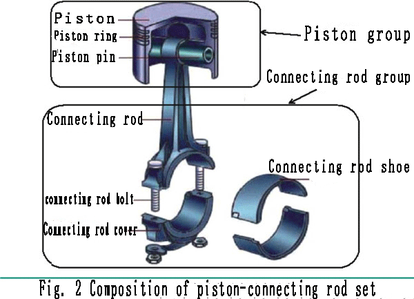
1. Piston connecting rod group: mainly composed of two parts: piston group and connecting rod group, as shown in Figure 2. This is basically the same as the air compressor. So what is the difference from an air compressor? Let's take a look at the next step by step breakdown!
1.1 The main functions of the piston group are:
① constitute a variable working volume;
② bear the gas pressure and transmit to the connecting rod;
③ heat dissipation. The piston group is composed of pistons, piston rings, piston pins and other parts.
1.1.1 The working conditions of the piston are generally high temperature, high pressure, high speed, and strong wear. Therefore, the material of the piston is required to have good high temperature strength and low density, small expansion coefficient, wear resistance, and good thermal conductivity. It is generally cast iron or aluminum alloy, and the material selection is basically the same as that of an air compressor. Next we look at the structure of the piston, as shown in Figure 3.

The structure of the piston mainly includes: the top; the main part of the combustion chamber; the head; the ring belt, also known as the sealing part; the skirt; the guiding part, which bears the side force.
As shown in Figure 4, there are 6 common types of piston tops, of which a style is the same as the common piston top styles of our air compressors, and the other 5 are completely different. Personal understanding is that air compressors pay more attention to converting power energy into stored air energy, and pay more attention to air compression and compression efficiency. Let's take a rough look at the design intent of the piston tops of different structures. This point is also a difference from the design of the air compressor.


The top of the piston is designed to be non-planar. The rough analysis generally has the following reasons: 1) Increase the contact area with the combustion gas and increase the heat absorption area; 2) Avoid the moving parts at the top, such as the valve; 3) To ensure The effective volume of the combustion chamber is required by the structural design.
Above the piston pin seat and below the top of the piston are called the piston head. As shown in Figure 5, this area is mainly matched with the piston ring. The main function is to seal; to prevent gas from entering the crankcase, oil into the combustion chamber, and heat conduction; to transfer most of the heat absorbed by the top from the head to the cylinder.
The design of piston rings and ring grooves has certain principles. The number of piston rings depends on the engine speed and the highest cylinder pressure. High-speed engines have fewer rings, and gasoline engines have fewer rings than diesel engines. Generally, gasoline engines use two gas rings and one oil ring; diesel engines use three gas rings and one oil ring; low-speed diesel engines use 3 to 4 gas rings. As the number of rings decreases, the friction loss is small. For the ring groove, the temperature of the piston ring is high during the working process, and the aluminum alloy piston is subject to high temperature hardness and easy to wear. In order to improve the wear life of the ring groove, a ring groove retainer is generally designed. The ring groove retainer generally uses austenitic cast iron with a thermal expansion coefficient close to that of aluminum alloy, which can increase the life of the ring groove by 3 to 5 times. Since the piston head is the entire heat accumulation area, how do we design to reduce the thermal load on the piston head?
Generally, there are three measures: 1) the heat insulation groove above the first ring groove;
2) thickening the head, so that the heat absorbed at the top can be easily transferred through the air ring; 3) the top spray cooling: free jet cooling; Strong cooling oil cavity
System cooling (generally the temperature of the first ring groove should not exceed 225℃).
The last component of the piston group is the piston skirt, as shown in Figure 6. Its main function is to guide and bear the side force. When designing, the gap between the skirt and the cylinder is generally required to be as small as possible; the cross section of the skirt is generally elliptical, and the direction of the piston pin is the short axis; the longitudinal section is small in the top and large in the bottom (high temperature above, large expansion), or convex shape (Bucket type, so that the piston can be well lubricated when moving up and down), the purpose is to compensate the elliptical deformation of the skirt.

The main reasons for the deformation of the piston skirt are:
①The metal heats up unevenly;
②The gas force causes the skirt to expand outward along the pin axis;
③The lateral force causes the skirt to deform and the pin axis to extend. The skirt is deformed in an elliptical shape when working, and the clearance with the cylinder is uneven.
Measures to prevent the deformation of the skirt: automotive gasoline engines:
①Open П-shaped or T-shaped elastic grooves on the skirt;
②Install Hengfan steel sheet on the pin seat to restrain thermal expansion.
Measures to prevent the deformation of the piston skirt of diesel engines: ①The skirt is inlaid with cylindrical steel;
②The skirt is made into an inverted ellipse;
③In the height direction, the diameter is small and large. It is preferably a convex shape with good lubrication.
There is also a position on the piston for installing the piston pin called the piston pin seat, as shown in Figure 7. Function: The gas force that the piston bears is transmitted to the connecting rod through the piston pin. The piston pin axis is usually located in the center plane of the piston. High-speed gasoline engines usually adopt an eccentric arrangement to reduce the knocking noise generated when the piston reverses pressure near the top dead center. As shown below. This design is also applied in high-end air compressor products.

1.1.2 Piston rings are divided into gas ring and oil ring. Piston ring materials: cast iron and steel. Porous chromium plating, molybdenum spraying, tin plating, phosphating, etc. are often used.

The gas ring is also called the compression ring. Its main functions are:
1) Sealing, preventing high temperature and high pressure gas in the cylinder from leaking into the crankcase; 2) Heat transfer, transferring the heat from the top of the piston to the cylinder wall. The gas ring can be divided into the following categories according to the shape of the cross section: 1) Micro-cone surface ring: good running-in, the cone angle is usually in the range of 30'~60', and it cannot be reversed when matched, otherwise the oil consumption will double , The second gas ring of Xiali car engine is a micro-cone ring; 2) Twisted ring: good sealing and running-in performance; 3) Trapezoidal ring: good anti-gelling performance, the top angle is usually 15; with automatic removal The role of carbon deposits is generally used to strengthen the first ring of diesel engines; 4) Barrel surface ring: The outer circular surface is convex arc, and the arc contacts when working. The tensile cylinder is good, and the upper and lower sides of the ring are wedge-shaped, which is easy to form liquid lubrication. The first gas ring of Xiali car engine and Fukang car engine is barrel surface ring, and the first gas ring of Jetta car engine is barrel surface twisted ring.
The oil ring is divided into three types according to the structure: a. Ordinary oil ring; b. Oil ring with expansion ring; c. Oil ring with coil spring expansion ring. Both Jetta and Xiali cars use combined oil rings. According to the cross-sectional shape, it can be divided into the following five types:
1) combined type;
2) spiral spring type;
3) slotted type;
4) chamfering direction is the same;
5) chamfering direction is different.
The main functions of the oil ring: oil distribution and oil scraping; upward oil distribution and downward oil scraping.

1.1.3 The main function of the piston pin is connection and force transmission, so the piston pin is required to have sufficient rigidity and fatigue strength, and the surface wear resistance should be good. Piston pin structures are mostly hollow cylinders, and most of the matching forms are; full-floating; and dynamic matching, generally using retaining rings for axial positioning. Precautions for the assembly of the piston pin: In order to ensure the proper clearance between the piston pin and the pin seat hole at high temperature during operation, some engines have an interference fit between the piston pin seat and the piston pin at room temperature. The piston needs to be assembled before assembly. After heating to 70-90; then gently push the piston pin into the pin seat. Some piston pins are assembled in cold state without heating the piston, but they need to be assembled in groups according to the piston pin hole and piston pin size.
1.2 The main functions of the connecting rod group are: ①transmitting force;
②motion conversion. The connecting rod group is generally composed of connecting rod body, connecting rod cover, connecting rod bushing, connecting rod bearing bush, connecting rod bolt and so on. Working conditions: withstand the impact of alternating loads. Medium carbon steel and alloy steel with higher fatigue strength and impact toughness are commonly used as materials.
The connecting rod components are divided into three parts:
① connecting rod small end; thin-walled round ring, with thin-walled copper sleeve inside, splash lubrication;
② connecting rod body: long rod, generally the cross-section of the connecting rod is designed into an I-shaped, small The large arc of the head and the big head is excessive to avoid stress concentration, and the piston assembly and the crank assembly are connected separately;
③The connecting rod big head:
For the assembly that needs to be separated, use flat cut or oblique cut. The positioning measures for the big end of the connecting rod include:
① serrated positioning;
② round pin positioning;
③ sleeve positioning;
④ stop positioning. The inner bearing bush of the connecting rod big-end hole is also made into a separate type, generally the outer layer is steel, and the inner layer is cast with a wear-resistant alloy layer.
In recent years, a new type has been developed; fracture location; method. Using the natural section of the fracture for positioning, FAW-Volkswagen Jetta EA113 five-valve engine high-carbon forged steel connecting rod adopts fracture positioning. When connecting rods are assembled, they are generally grouped according to the mass of the connecting rods in grams, and the same group of connecting rods is used for the same engine.

The structure of the connecting rod of the V-type and W-type internal combustion engine is slightly different from that of the in-line type, and the connecting rod of the air compressor also follows this rule.
2. Crank flywheel group: mainly composed of crankshaft, flywheel, balance weight, shock absorber and transmission gear, etc.
3.2.1 The main functions of the crankshaft: 1) Convert the force transmitted by the connecting rod into torque and send it to the vehicle transmission;
2) Drive the valve mechanism;
3) Drive other auxiliary devices. The crankshaft is composed of a front end (free end), a rear end (power output end) and several cranks. Front end: Stepped shaft section, equipped with transmission gears, pulleys, seals, etc.
Some are equipped with torsion shock absorbers. Rear end of crankshaft: power output end. Structure: flange or spline. Crank: Also known as crank, it consists of crank pin, crank arm and main journal.


The crank layout of internal combustion engines is now mostly inline with 3 and 4 cylinders; V with 6 and 8 cylinders; and a very small number of W type 12 cylinders, as shown in Figure 14. The number of cranks is related to the number of cylinders and the arrangement type: the inline type is equal to the number of cylinders; the V-shape is half of the number of cylinders.
The structure of the crankshaft of the W-type engine is complicated. The left and right cylinders are arranged on different crankshafts, and two connecting rods are installed on each crank in the form of staggered cranks.

The crank is divided into full support and non-full support according to the number of main journals. The crankshaft journal structure is mostly hollow, reducing mass and centrifugal force; in order to reduce stress concentration, the main journal, crank pin and crank arm are connected by transitional arcs, as shown in Figure 14. The counterweight of the crank is designed to balance the centrifugal force and moment of rotation, or balance the force of reciprocating inertia and moment. The arrangement of the balance weight is related to the number of cylinders, the arrangement of the cylinders and the shape of the crankshaft.
The shape of the crankshaft is the relative position between the cranks, that is, the crank angle. It is related to the number of cylinders, cylinder arrangement and number of strokes. The following main factors should be considered when determining the crank angle: 1) In order to make the engine work smoothly, the firing interval angles of each cylinder should be as equal as possible. For example, the four-cylinder engine should be 180, and the three-cylinder engine should be 240; 2) In order to reduce the main shaft diameter and the main bearing load, two adjacent cylinders should be fired as discontinuously as possible; 3) The engine balance is good; 4) For the V-type engine, Consider alternately firing the left and right cylinders.
2.2 The main functions of the flywheel:
①store energy and release energy;
②reduce the unevenness of angular velocity;
③make the output torque uniform;
④help the internal combustion engine start and the vehicle start.
Structure:
①The mass is mostly concentrated on the wheel flange; in order to make the moment of inertia larger and the mass smaller;
②Generally, the flywheel is equipped with a ring gear and meshes with the starter motor;
③The flywheel is often engraved with various timing marks to adjust the relative phase.
Fourth, the force of the crank connecting rod mechanism
1. Gas force: Pg=pi; D2(p-p')/4

2. The friction force is negligible because its value is small.
3. Inertial force:
3.1 The reciprocating inertial force Pj is (the derivation process is omitted) Pj=mj(Rω2cosα; +Rω2λcos2α;) = Pj1+Pj2Pj The acting direction is along the cylinder centerline, either positive or negative;
3.2 Rotating inertial force (or rotating centrifugal force) Pr = The direction of action of mrRω2Pr is always the decomposition and transmission of the total force PΣ on the outward piston along the crank.
The forces acting on the crank connecting rod mechanism are Pg, Pj, Pr, and for multi-cylinder engines, there are also the moments formed. Among them, Pg is balanced inside the body; the reaction torque M formed by the side pressure; cannot be balanced (the proof is omitted), and will be transmitted to the engine support. Pj and Pr change periodically with α; these forces and moments are continuously transmitted to the fulcrum outside the body, causing the internal combustion engine to vibrate

Vibration will fatigue the occupants in the car, damage the brackets and loosen the connections, and cause accidents in severe cases. Some measures must be taken to balance unbalanced forces and moments to achieve balance or minimize vibration.
V. Conclusion Compared with the air compressor industry, the internal combustion engine industry has a relatively early industrial layout and relatively mature. It is also relatively mature for the research and application of certain general principles and institutions. Hope that we can design better air compressor products through differentiated comparison and learning.
