Detection and evaluation of dust removal and nitrogen addition equipment in the food processing field
Detection and evaluation of dust removal and nitrogen addition equipment in the food processing field
In the Midwestern United States, most food manufacturing plants use compressed air and on-site nitrogen production to produce and package a variety of foods. When the electricity price is 4.5 cents/KWh, the manufacturer's annual expenditure on the energy consumption of the compressed air system is $430,344.
This project mainly studies the air compression system in the food packaging process. The research results can reduce the gas flow of the factory by 689scfm and save $54,671 in cost. The project uses open air blowing, nitrogen leak repair and the use of air oscillators to maintain product movement.
Due to the limited number of words, this article will show the reader the results we have observed on the demand side of the compressed gas system, and will elaborate on the specific schemes for reducing the gas flow.
Compressed gas system evaluation
The factory has two compressor rooms. The core room provides compressed air for the factory's production area and the PSA nitrogen generator, and the other room provides compressed air for the bakery.
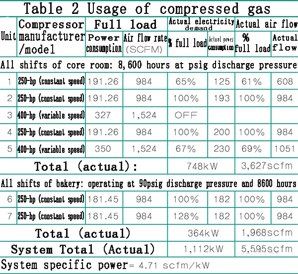
The compressed air system of the core computer room includes three 250-hp oil-free fixed-speed rotary screw air compressors. At the same time, they are connected to two 400-hp oil-free variable-speed rotary screw air compressors through pipelines. These five equipment The compressed gas is delivered to two large freeze dryers to achieve gas drying.
The other machine room consists of two 250-hp oil-free rotary screw compressors, and the compressor has a shunt HOC (hot pressing) drum-type gas dryer built in to dry the gas.
The compressed air systems in the two computer rooms work 8,600 hours per year. The load curve (air demand) of the system is relatively stable in all operating shifts. In general, the annual system gas flow is between 4,000scfm and 6,200scfm, with an average of about 5,200 to 5,500scfm.
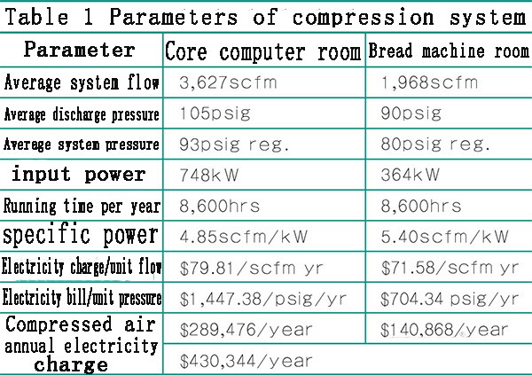
As shown in Table 1, the average system flow rate of the core computer room is 3,627scfm, the average air compressor discharge pressure is 105 psig, and the average system pressure is 9 psig. The total input power of the core computer room is 748kW, and the specific power is 4.85scfm/kW. The electricity bill per unit of compressed air is $79.81/scfm per year, and the electricity bill per unit of compressed air is $1,447.38 psig per year. The annual electricity bill for the core computer room is $289,476.
The average system flow rate of the bakery machine room is 1,968scfm, the average discharge pressure is 90psig, and the average system pressure is 80psig. The total input power of the machine room is 364kW, and the specific power is 5.4scfm/kW. The electricity bill per unit flow of compressed air is $71.58/scfm per year, and the electricity bill per unit of compressed air is $704.34 psig per year. The annual electricity bill for the core room is $140,868.
After the compressor's work analysis, the compression equipment is running well in both places. But just as we often encounter when evaluating compressed air, our team found that an air compressor may provide much less air flow than required when the power reaches the rated power. However, we can see from Table 2 that the actual demand for air flow (load) matches the power consumption of the unit, so this situation did not appear in the food factory.
Dust removal system evaluation: an unavoidable problem in food factories
In any food factory, the evaluation of the dust removal system is very important. In this food factory, we checked the use of compressed air in 12 dust collectors and found that the feed size of the dust collectors was appropriate and there was enough storage space between each dust collector. Demand control is very effective, and the bag of the dust collector is replaced at an appropriate time. In addition, the operation of these devices does not use timers, but even if low-pressure gas is passed into other nearby pipes or into the dust collector, it will not cause problems.
In a typical pulse jet dust removal system, after dust is collected by a cloth bag or comb eliminator, a dust block with a suitable size and structure will be formed, which can be flushed from the cloth bag with a pulse of compressed air. When the dust block is correctly removed from the dust collector, the system successfully removes the dust in the specified environment, and the cloth bag has a normal service life; but if the dust block cannot be effectively removed from the dust collector, the dust collector The filter will lose the function of dust removal and will greatly shorten the service life of the bag.
When the compressed gas feed condition of the equipment is normal, the demand controller can consume less air and achieve better results. However, if the demand controller is used without proper compressed air feed, it may consume more air and reduce the service life and performance of the bag. Therefore, the correct operation of the dust collector is essential to reduce costs and improve system efficiency. At the same time, there are also many dust collection systems that control the pulse of compressed air through timers. The operator sets the timer through specific conditions to effectively remove dust blocks and ensure the service life of the bag.
The design of the dust removal system specifies the inlet pressure of the manifold and pulse valve required for effective dust removal.
The pulse valve sends a given amount of compressed gas to the cloth bag at a predetermined speed to flush and clean the dust blocks on the cloth bag. The given air volume depends on the pressure of the compressed air injected by the pulse nozzle under a predetermined condition.
For each pulse, the dust collector must be at the correct (or close to it), stable and repeatable pressure level, especially when the timer is used to control the pulse. The operator can find the correct timing under the required intake pressure through experiments. But once the pressure changes, the performance of the system may deteriorate.
It is a frequent problem that the dust block is difficult to remove from the cloth bag. The main reason may be that the pulser sends a pulse to the cloth bag at an inappropriate time, or the time between two pulses is too long, which causes the dust block to accumulate and increase. It is difficult to remove effectively. This will not only shorten the service life of the bag, but also greatly reduce the performance of the system. The basic reasons for this situation are:
1. The timer setting of the operating condition is incorrect. The actual need to determine the optimal timer setting may vary with the production of products, and even with seasonal changes. Therefore, the timer needs to be carefully set from the beginning and monitored regularly.
2. The lack of sufficient storage space or sufficient air supply at the air inlet makes the system have to reduce the gas pressure to meet the air volume required by the pulse.
3. If the air intake pipe of the dust collector is too small, it will also produce an effect similar to the insufficient air supply.
4. A regulating valve that is too small or inappropriate can not handle the gas flow required by the dust collector.
All these conditions will cause the gas flow to be restricted. The reason for these situations is that the proper gas flow rate was not determined for the dust removal operation before installation or before certain operation changes. The size of the intake pipe, the size of the regulating valve, and the amount of intake need to refer to the specific gas of the system; the actual flow; instead of the so-called average flow.
Average flow; is the flow of compressed air (in cubic feet per minute), regardless of the amount of air required by the process or input to the system. The actual flow rate refers to the air flow rate (in cubic feet per minute) required by the system. If in a short time, even if the air volume required by the system is relatively small, there may still be a large actual flow. This is the characteristic of the dust collector.
The program controller can have a very significant impact on the actual flow required by the system. For example, a dust collector equipped with six pulse valves can use 3.5 cubic feet of compressed air, with each pulse exceeding half a second.
If these two different flow rates are used to control the flow rate of the air supply line, they will have similar differences in their influence on the size of the regulator. Entering the manifold at a high flow rate will cause additional pressure loss, which will affect the performance of the pulse cleaner. If necessary, a similar effect can also be used to change the size of the air receiver to reduce the pressure drop of the system and the air supply line.
Recommendations for quality pressure gauges
We usually recommend installing a mass pressure gauge near the inlet of the dust collector of each gas supply line. Observe the pressure of the pulse impact on the meter. If the pressure drop is too high, it is necessary to find out the cause. Understand the dust collector specifications, gas flow per pulse, pulse feed pressure time, cycle time between pulses, etc. Then calculate the air flow of the system, check whether the pipe diameter and storage space are appropriate, to decide whether to increase the storage space. When there is a problem with the control diaphragm or pipe connection, there will be a large amount of compressed gas leakage (10 to 15 cubic feet per minute or more). Such leaks are often difficult to find and difficult to repair.
Choosing the appropriate size and storage device for the dust collector can transform operations that require a large volume of gas in a short period of time into operations with a very low average flow rate. If short high demand pulses (less than 1 minute) are not required, a regulating valve should be installed after the receiver.
Appropriate increase in storage space is not only considered from the energy level, but also from the air quality level. Correctly controlling the dust collector can reduce the impact of the pressure drop at the nozzle on the surrounding system, and at the same time can improve the performance of the dust collector and extend the service life of the bag. Dust collectors are an important source of leakage and are difficult to detect. The impulse control diaphragm often leaks, and the electronic airflow alarm can detect this problem visually and send out signals from a long distance.
After the system is reset and stabilized, check the operation of each dust collector to ensure that the cloth bags are replaced in a timely manner, to control work requirements, and to ensure that there are no adverse effects between adjacent equipment.
Solve the problem of open blowing and achieve the best blowing effect
The compressed air system in two areas of the factory was audited and thoroughly evaluated, and several methods were found to reduce air flow. One of them is the optimization of open aeration.
The turbulent compressed air is sprayed directly from the pipeline, which will waste a large amount of compressed air, violate the noise regulations in the Occupational Safety and Health Standards (OSHA), and it is far from reaching the pressure requirements. The use of air jets and nozzles that induce air flow instead of open air blowing can reduce noise levels, reduce the use of compressed air, and generally improve the efficiency and quality of blowing operations.
The appropriate Venturi amplifier and controller are installed in the factory. And began to use more mechanical means to clean up dust blocks to reduce the use of compressed air. These optimization measures have reduced airflow demand by 305scfm and annual power consumption by 539,644kWh, which is equivalent to annual savings of $24,284.
There are many air jet devices and products that induce airflow on the market. But the test of one nozzle may be different from another nozzle of the same manufacturer, but the difference is not significant. Here are the main points to remember:
5. During the blowing process, pressure thrust (psig) is required to loosen the dust to be blown off.
6. Once the air leaves the blowing device, the thrust will quickly dissipate.
7. In the blowing process, the total air volume (cfm), compressed air and induced air are essential for the blowing operation.
8. Use expensive compressed air as the last resort; machinery, hydraulics, etc. are always more energy-saving and often safer.
9. All blown air should be adjusted to the lowest effective pressure. Higher pressure is accompanied by greater flow, which is often unnecessary, because higher pressure makes production costs more expensive. The compressed air provided by the blower will be more economical.
10. Whenever possible, Venturi air amplifier nozzles should be used as much as possible; appropriately select the air thrust and volume provided, which will usually reduce at least 50% of the blown air, and use the saved air to other more valuable On the job.
11. When the production is not needed, all the air blowing process can automatically stop.
12. When the air produced by the blower is available or economically feasible, compare its net energy cost with alternative energy sources.
Better nitrogen control, better air vibration method
The second method of reducing air flow is focused on plant nitrogen (N2). After observing 20 bag assembly operations in one area, the research team found that except for one product, most of the other bagging systems use nitrogen. Nitrogen is prepared on site by an automatic control nitrogen generator with a capacity of 580-scfm, with liquid N2 as a backup. The amount of nitrogen used is 320-350 scfm, and the purity is between 99.7% and 99.8%. The generation ratio of nitrogen is about 5:1. Every 60 to 65 seconds, 1750 cubic feet of air is used to generate 350 cubic feet of nitrogen. Usually, when the production line stops, the supply of nitrogen is still going on. During a field visit, about 7 bagging machines were left on the production line that was not in operation, and each bagging machine contained 3 to 20 cubic feet of nitrogen.
The factory uses automatic shutdown control to solve this problem. When nitrogen is not needed, it will automatically stop the supply of nitrogen. It also installed a control valve to adjust the amount of nitrogen used. This optimization measure reduces the airflow demand by 300scfm and reduces the annual power consumption by 530,800kWh, which is equivalent to an annual saving of $23,886.
Finally, the factory implemented a better method, using air vibrators to keep products or packages moving or separating. If the air usage of the air vibrator used in a factory is about 10 cfm per unit, then a similar electric vibrator to produce the same product requires 2.5-hp or higher power, which may require 0.25-hp Power input around. With this optimization measure, airflow demand is reduced by 84scfm, and annual power consumption is reduced by 144,480kWh, which is equivalent to annual savings of $6,501.
in conclusion
The food packaging business achieved its main goal, which is to implement cost-effective methods to reduce the need for compressed air in core production areas and bakeries, and save costs in the process. We will continue to study and implement new methods to reduce the demand for compressed air and improve supply operations to achieve more savings.
Subscribe to relevant news content? Subscription
Unsubscription


