


-min.png)
Figure 1: Variable Frequency Drives (VFDs).
1. Working Principle
1.1 Standard Configuration
The first stage of a Variable Frequency AC Drive, or VFD, is the Converter. The converter is comprised of six diodes, which are similar to check valves used in plumbing systems. They allow current to flow in only one direction; the direction shown by the arrow in the diode symbol. For example, whenever A-phase voltage (voltage is similar to pressure in plumbing systems) is more positive than B or C phase voltages, then that diode will open and allow current to flow. When B-phase becomes more positive than A-phase, then the B-phase diode will open and the A-phase diode will close. The same is true for the 3 diodes on the negative side of the bus. Thus, we get six current “pulses" as each diode opens and closes. This is called a “six-pulse VFD", which is the standard configuration for current Variable Frequency Drives.

Figure 2: Standard configuration of a VFD.
1.2 Working Process
Let us assume that the drive is operating on a 480V power system. The 480V rating is “rms" or root-mean-squared. The peaks on a 480V system are 679V. As you can see, the VFD dc bus has a dc voltage with an AC ripple. The voltage runs between approximately 580V and 680V.

Figure 3: The VFD dc bus has a dc voltage with an AC ripple.
We can get rid of the AC ripple on the DC bus by adding a capacitor. A capacitor operates in a similar fashion to a reservoir or accumulator in a plumbing system. This capacitor absorbs the ac ripple and delivers a smooth dc voltage. The AC ripple on the DC bus is typically less than 3 Volts. Thus, the voltage on the DC bus becomes “approximately" 650VDC. The actual voltage will depend on the voltage level of the AC line feeding the drive, the level of voltage unbalance on the power system, the motor load, the impedance of the power system, and any reactors or harmonic filters on the drive.
The diode bridge converter that converts AC-to-DC, is sometimes just referred to as a converter. The converter that converts the dc back to ac is also a converter, but to distinguish it from the diode converter, it is usually referred to as an “inverter". It has become common in the industry to refer to any DC-to-AC converter as an inverter.
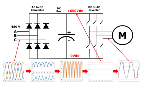
Figure 4: The diode bridge converter that converts AC-to-DC.
When we close one of the top switches in the inverter, that phase of the motor is connected to the positive dc bus and the voltage on that phase becomes positive. When we close one of the bottom switches in the converter, that phase is connected to the negative dc bus and becomes negative. Thus, we can make any phase on the motor become positive or negative at will and can thus generate any frequency that we want. So, we can make any phase be positive, negative, or zero.
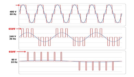
Figure 5: The output from the VFD is a rectangular wave form.
Notice that the output from the VFD is a “rectangular" wave form. VFD’s do not produce a sinusoidal output. This rectangular waveform would not be a good choice for a general purpose distribution system, but is perfectly adequate for a motor.
If we want to reduce the motor frequency to 30 Hz, then we simply switch the inverter output transistors more slowly. But, if we reduce the frequency to 30Hz, then we must also reduce the voltage to 240V in order to maintain the V/Hz ratio. How are we going to reduce the voltage if the only voltage we have is 650VDC?
This is called Pulse Width Modulation or PWM. Imagine that we could control the pressure in a water line by turning the valve on and off at a high rate of speed. While this would not be practical for plumbing systems, it works very well for VFD’s. Notice that during the first half cycle, the voltage is ON half the time and OFF half the time. Thus, the average voltage is half of 480V or 240V. By pulsing the output, we can achieve any average voltage on the output of the VFD.
2. Why Should I Use A VFD

Figure 6: Various types VFD.
2.1 Reduce Energy Consumption and Energy Costs
If you have an application that does not need to be run at full speed, then you can cut down energy costs by controlling the motor with a variable frequency drive, which is one of the benefits of Variable Frequency Drives. VFDs allow you to match the speed of the motor-driven equipment to the load requirement. There is no other method of AC electric motor control that allows you to accomplish this.
2.2 Increase Production Through Tighter Process Control
By operating your motors at the most efficient speed for your application, fewer mistakes will occur, and thus, production levels will increase, which earns your company higher revenues. On conveyors and belts you eliminate jerks on start-up allowing high through put.
2.3 Extend Equipment Life and Reduce Maintenance
Your equipment will last longer and will have less downtime due to maintenance when it’s controlled by VFDs ensuring optimal motor application speed.
Related Info
How To Measure Output Voltage From A VFD To A Motor?What is A VFD?
VFD Types And Applications?
How to Install a HMI and 4 Common Failures?
