


Figure 1: Radial piston motor
A hydraulic piston motor is a type of hydraulic motor. How does a hydraulic piston pump work? That is the working medium (hydraulic oil, etc.) acts on the end face of the piston or plunger and makes them reciprocate in a straight line. Through the motion conversion mechanism (swash plate, cam, crank, etc.), the reciprocating motion of the plunger is converted into a circular motion of the output shaft.
According to the positional relationship between the piston and the transmission shaft, the hydraulic piston motor is divided into two categories: axial piston hydraulic motor and radial piston hydraulic motor.
1. Radial Piston Hydraulic Motor
The radial piston hydraulic motor is a low-speed and high-torque motor. Its main features are large output torque, up to several thousand to tens of thousands of N m, and good low-speed stability. Generally, it can run smoothly below 10r/min, and some can as low as 0.5r/min, so it can be directly connected to the working mechanism. Radial piston motors are usually divided into two types, namely single-acting type and multi-acting type.
1.1 Types of Radial Piston Hydraulic Motors
When the rotor of the single-acting radial piston motor rotates a single revolution, each piston reciprocates once. Its main shaft is an eccentric shaft.
The multi-acting radial piston motor uses a cam ring with a special inner curve as a guide rail. The rotor rotates a single revolution, and each piston reciprocates many times. The number of curves is the number of actions per revolution.
|
Radial piston motor |
1.According to number of actions |
Single acting radial piston type (crankshaft type) |
Crankshaft connecting rod type |
|
Swing cylinder type |
|||
|
Connecting rod-less type |
|||
|
Multi-acting radial piston type (internal curve type) |
Piston transmission type |
||
|
Beam transmission type |
|||
|
Roller transmission type |
|||
|
Connecting rod transmission type |
|||
|
2.According to whether the flow can be adjusted or not |
Variable displacement radial piston motor |
|
|
|
Fixed displacement radial piston motor |
|||
|
3.According to flow distribution methods |
Shaft distribution type |
|
|
|
End-face distribution type |
|||
|
Slide-valve distribution type |
|||
|
4.According to fixed methods |
Housing fixed--shaft rotating type |
|
|
|
Shaft fixed--shell rotating type |
Table 1: Types of radial piston motors.
1.2 How Radial Piston Hydraulic Motors Work
As there are two main types of radial piston motors, single-acting and multi-acting types, the working principles of them are introduced below.
Working principle of single-acting radial piston motor
The working principle of the single-acting radial piston motor, as shown in Figure 2, the crankshaft connecting rod radial piston motor has five (or seven) cylinders radially and uniformly arranged along the circumference of the housing 1.
The piston 2 in the cylinder is connected with the connecting rod 3 through a ball hinge, and the end of the connecting rod is in contact with the eccentric wheel of the crankshaft 4. The center of the eccentric wheel is O1, the center of rotation of the crankshaft is O, and the eccentric distance between the two is e.
One end of the crankshaft is the output shaft, and the other end is connected to the distribution shaft 5 through a cross-shaped coupling. The two sides of the "partition wall" on the distribution shaft are the oil inlet and the oil discharge chambers respectively.
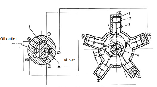
Figure 2: Working principle diagram of single-acting radial hydraulic motor piston.
1—Housing; 2—Piston; 3—Connecting rod; 4—Crankshaft; 5—Distribution shaft; O—The center of the transmission crankshaft; O1—The center of the eccentric wheel
After the high-pressure oil from the oil source enters the motor oil inlet chamber, and is introduced into the corresponding piston cylinders ①, ②, and ③ through the slots ①, ②, and ③ of the casing. The hydraulic pressure P generated by the high-pressure oil acts on the top of the piston and is transmitted to the eccentric wheel of the crankshaft through the connecting rod.
For example, the force of the piston cylinder ② acting on the eccentric is N, and the direction of this force is along the center line of the connecting rod, pointing to the center O1 of the eccentric wheel. The acting force N can be decomposed into the normal force Ff (the action line coincides with the connecting center line 001) and the tangential force F. The tangential force F produces torque on the rotation center O of the crankshaft, causing the crankshaft to rotate counterclockwise around the center line O.
Piston cylinders ① and ③ are also similar to this, but their positions relative to the main shaft are different, so the magnitude of the generated torque is different from that of cylinder ②. The total torque of the crankshaft rotation is equal to the sum of the torques generated by the piston cylinders (①, ② and ③ in the case shown in Figure 2) that are connected to the high pressure chamber.
When the crankshaft rotates, the volumes of cylinders ①, ②, and ③ increase, while those of ④ and ⑤ become smaller. The oil is discharged through the oil passages ④ and ⑤ of the casing via the oil discharge chamber of the distribution shaft 5.
When the distribution shaft rotates synchronously with the crankshaft over an angle, the “partition wall" of the distribution shaft closes the oil passage ③. At this time, the cylinder ③ is not connected to the high and low pressure chambers, while cylinders ① and ② are connected to high pressure oil, which make the motor generate torque, and cylinders ④ and ⑤ drain oil.
Since the distribution shaft rotates with the crankshaft, the oil inlet and the oil discharge chambers are connected with each piston in sequence, thereby ensuring the continuous rotation of the crankshaft.
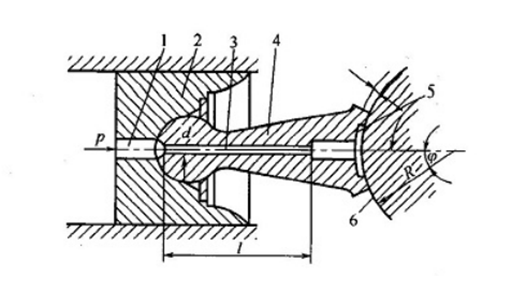
Figure 3: Connecting rod ball-hinged set.
1 - Through-hole; 2 - Piston; 3 - Damping tube; 4 - Connecting rod; 5 - Connecting rod slider; 6 - Crankshaft (eccentric wheel)
Working principle of the multi-acting radial piston motor
As shown in Figure 3, in the multi-acting radial piston motor, the cam ring 1 as the guide rail is composed of exactly the same X-section (X=6 in the figure) curves, each of which consists of symmetrical oil inlet and return segments.
There are Z uniformly distributed piston cylinder holes in the cylinder body, the bottom of which is communicated with the distribution holes of the distribution shaft 4. The oil distribution shaft has 2X distribution holes, X holes are connected to the high pressure oil, corresponding to the oil inlet section of the guide rail curve, and the other X holes, corresponding to the oil return section of the curve, are connected to the oil return circuit.
When working, under the action of pressure oil, the roller is pressed against the guide rail. The force N is the reaction force of the curved surface of the guide rail to the roller, its radial component force F is balanced with the hydraulic pressure, and the tangential component force F' is transmitted to the cylinder through the beam to form the torque that drives the external load.

Figure 4: Working principle diagram of multi-acting radial piston motor.
1—Cam ring; 2—Cylinder, 3—Beam, 4—Distribution shaft, 5—Roller
When the direction of the motor oil inlet and outlet is reversed, the motor reverses. The tangential component force F' of the roller reaction force N shown in Figure 4 is transmitted to the cylinder through the beam, which is called the beam transmission motor;
If the tangential component force is transmitted to the cylinder through the piston, it is called a piston transmission motor;
If the tangential component force is transmitted to the cylinder block by the other two rollers on the same beam through the guide side plate, it is called a roller transmission motor;
If the force is transmitted through the interaction between the steel ball in the piston ball socket and the guide rail, it is called a ball-piston internal curve motor.
1.3 Advantages and Disadvantages of Radial Piston Motors
The main advantages of radial piston hydraulic motors compared to other hydraulic motors:
①Relatively small axial size.
②Large displacement and low speed.
③Good stability at low speed. It can run smoothly below 10r/min, and some can be as low as 1.5r/min.
④The output torque is large, which can reach thousands or even tens of thousands of N·m.
⑤ It can be directly connected to the working mechanism it drags without the need for a speed reduction device.
Shortcoming:
①Large radial size
②Complex structure, large volume, low power density
The single-acting radial piston hydraulic motor has the advantages of simple structure, good manufacturability and low cost. However, in the case of the same displacement, the single-acting radial piston hydraulic motor, compared with the multi-acting motor, has an increased structural size and a larger unbalanced radial force acting on the rotor, which requires a bearing with a larger capacity. It has the pulsation of output speed and torque, and the low-speed stability are not as good as multi-acting motors, but generally allowing higher speeds than multi-acting motors.
Related Info
FAQs on Hydraulic MotorHow to Maintain Circuit Breaker?
Choose the Right Circuit Breaker
Differences between Circuit Breaker and Isolator Switch
How Does a Hydraulic Drive Motor Work?
