


The refrigerator solenoid valve is mainly used to change the flow direction of the refrigerant to control the cooling temperature of different compartments of the refrigerator (refrigerator compartment, freezer compartment, and variable temperature compartment). Common refrigerator solenoid valves mainly include two-way solenoid valves, two-position three-way solenoid valves, three-position four-way solenoid valves, six-position five-way solenoid valves, etc.
1. Structure and Working Principle of the Two-Way Solenoid Valve
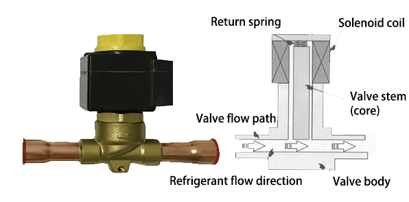
The two-way solenoid valve is mainly composed of valve flow path, solenoid coil, valve stem (iron core), return spring, etc., as shown in the figure below.
1.1 Working Principle of Two-Way Solenoid Valve

● When the two-way solenoid valve is energized, the valve stem will be affected by the action of the solenoid coil and overcome the elastic force of the spring, moving upward so that the valve is open and the refrigerant can flow smoothly.
● When the solenoid coil loses power, the valve stem moves downward under the action of the return spring, closing the valve, thus blocking the flow of refrigerant and preventing high-pressure refrigerant from flowing back.
2 Structure and Working Principle of the Two-Position Three-Way Solenoid Valve

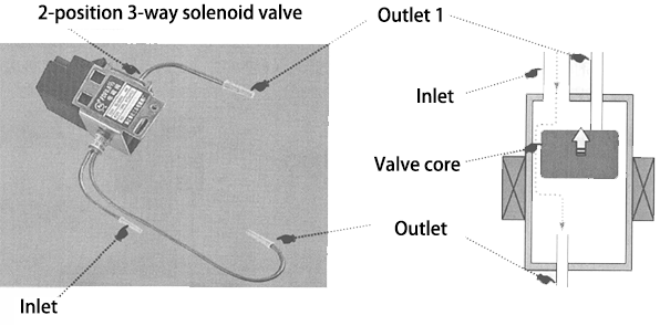
The two-position three-way solenoid valve is mostly used in dual-temperature dual-control or multi-temperature multi-control refrigerators. The following figure shows the physical appearance and internal structure of the two-position three-way solenoid valve. As can be seen from the figure, the two-position three-way solenoid valve is mainly composed of an inlet, two outlets, a valve core, etc.
2.1 Working Principle of Two-Position Three-Way Solenoid Valve
The working principle diagram of the two-position three-way solenoid valve is as follows:

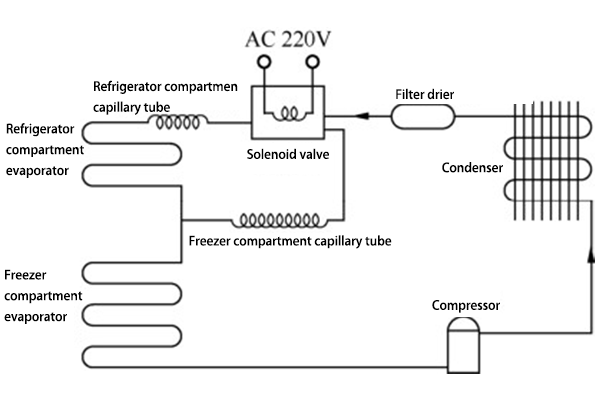
● When the two-position three-way solenoid valve is energized, the solenoid valve core moves to block the outlet connected to the capillary tube in the refrigerator compartment, allowing the inlet end to be connected to the capillary tube in the freezer compartment.
● When the power supply to the solenoid valve disappears, the solenoid valve core blocks the outlet connected to the capillary tube in the freezer compartment, allowing the inlet end to be connected to the capillary tube in the refrigerator compartment.
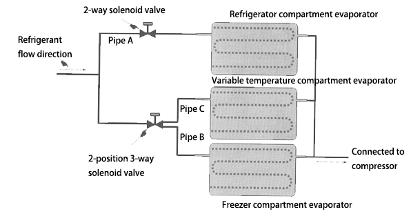
The figure below shows the specific applications of two-way solenoid valves and two-position three-way solenoid valves. When the control circuit turns on the two-way solenoid valve, the evaporator in the refrigerator compartment starts cooling; when the two-way solenoid valve is turned off, the refrigerator compartment stops cooling.
3. Structure and Working Principle of Three-Position Four-Way Solenoid Valve

The three-position four-way solenoid valve has an inlet and three outlets. The inlet end is connected to the filter dryer, while the outlet ends are connected to the capillary tubes respectively in the refrigerator compartment, the freezer compartment, and the variable temperature compartment, as shown below.
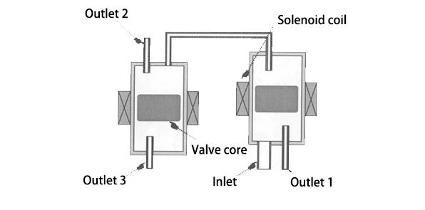
3.1 Working Principle of Three-Position Four-Way Solenoid Valve
The working principle diagram of the three-position four-way solenoid valve is as follows:
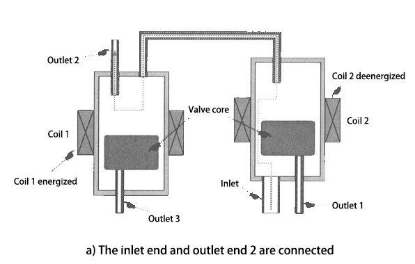
The three-position four-way solenoid valve has two sets of coils. When coil 1 is energized and coil 2 is de-energized, the inlet end and outlet end 2 are connected, and the outlet end 1 and outlet end 3 are blocked.

When both coil 1 and coil 2 lose power, the inlet end and outlet end 3 are connected, and the outlet end 1 and outlet end 2 are blocked.

When coil 1 is de-energized and coil 2 is energized, the inlet end and outlet end 1 are connected, and the outlet end 2 and outlet end 3 are blocked.
The figure below shows the specific application of a three-position four-way solenoid valve in the refrigerator refrigeration pipeline:
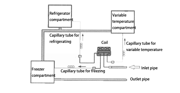
● When the solenoid valve coil 1 is energized and the coil 2 is de-energized, the solenoid valve outlet pipe B is connected, and the outlet pipes A and C are blocked. At this time, the refrigerator and freezer compartments are working.
● When both the solenoid valve coil 1 and coil 2 also de-energized, the solenoid valve outlet pipe C is connected, and the outlet pipes A and B are blocked. At this time, the freezer compartment is working.
● When the solenoid valve coil 1 is de-energized and the coil 2 is energized, the solenoid valve outlet pipe A is connected, and the outlet pipes B and C are blocked. At this time, the variable temperature compartment and the freezer compartment are working for cooling.
