


Figure 1: Check valves.
Depending on the design of the Check Valve, they will operate slightly differently. The most common check valve is a spring loaded in-line check valve, however, we will discuss multiple types below.
1. In-line Spring Loaded Check Valve

Figure 2: In-line spring loaded check valve working components: valve body (A), disc (B), spring (C), and guide (D).
In-line spring loaded check valves are common, easy to understand, and have a simple design. Figure 1 shows an example of a spring loaded in-line check valve and Figure 2 shows the main components with arrows showing flow direction. When flow enters the input port of the valve, it has to have enough pressure (force) to overcome the cracking pressure and the spring force. Once overcome, it pushes the disc, opening the orifice and allowing flow to move through the valve. When the input pressure is no longer high enough, or there is a backpressure, then the backpressure and spring push the disc against the orifice and seal the valve shut. The spring, along with the short travel distance for the disc, allows for quick reaction time for closing. This valve design also prevents against pressure surges in the line, and therefore, also prevents a water hammer from occurring. Common types of spring loaded in-line check valves are also called ‘nozzle check valves’ or ‘silent check valves.’ They can be installed in a vertical or horizontal orientation. However, since they are in-line to the system, they have to be fully removed from the line to be inspected and/or perform maintenance.
2. Spring Loaded Y-check Valve

Figure 3: Y-check valve.
Spring loaded y-check valves operate very similar to in-line spring loaded check valves. The difference is that the spring and movable disc are positioned at an angle. This creates a ‘y’ shape, hence the name of the valve. It works the exact same as an in-line valve, but since the moveable components are at an angle it can be inspected and serviced while it is still connected to the system. However, they are larger and take up more room within the system.
3. Ball Check Valve
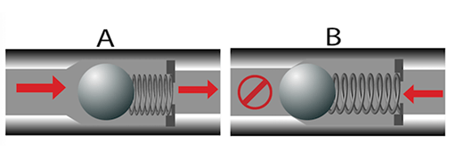
Figure 4: Ball check valve in the open position allowing flow (A), and in the closed position preventing backflow (B).
A ball check valve uses a free-floating or spring-loaded ball that rests on the sealing seat to close the orifice. The sealing seat is normally conically tapered in order to guide the ball into the seat and create a positive seal, thereby, stopping reverse flow. When the pressure of the fluid in the inlet side exceeds the cracking pressure, the ball is dislodged from its seat and allows flow to occur. When the inlet pressure doesn’t exceed the cracking pressure, or there is back pressure, the ball will close with the back pressure or via the spring, effectively closing the orifice.
4. Diaphragm Check Valve

Figure 5: Diaphragm check valve normally open (left), open with inlet pressure (middle), and closed due to backflow pressure (right).
Diaphragm check valves consist of a rubber diaphragm that flexes open when the inlet pressure is increased. Normally, these types of valves have a free-floating self-centering diaphragm, which makes them normally open (NO). These means that there is no “cracking pressure", however, they can be normally closed (NC) and then it requires an inlet pressure to overcome the diaphragms elasticity. Figure 5 on the left shows a normally open diaphragm check valve as there is ‘minimal’ inlet pressure and the media still gets through. As inlet pressure increases, the diaphragm will flex open more allowing flow through. Due to the normally open nature, diaphragm check valves are ideal for low-pressure or vacuum applications.
5. Lift Check Valve

Figure 6: Lift check valve left in open position, right in closed position.
A lift check valve consists of a guided disc that raises (lifts) up off of the valve seat to allow media flow. It requires a cracking pressure to overcome gravity and/or a spring and the guide keeps the disc in a vertical line, so that the disc can be re-seated with the correct alignment and seal. Most commonly, lift check valves require the media to make a 90-degree turn. But there are lift check valves that are in-line or at an angle. As the inlet pressure decreases below the cracking pressure or there is a backpressure, the valve will close by gravity, spring, and/or by using the backpressure. If there is no spring to assist in closing, mounting orientation in regard to gravity is important to ensure that the disc will swing shut with gravity.
6. Swing Check Valve
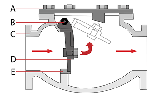
Figure 7: Swing check valve. Bolted bonnet (A), hinge or trunnion (B), valve body (C), disc (D), seal (E).
Swing check valves are also commonly referred to as ‘tilting-disc’ check valves. They consist of a disc that is on a hinge (or trunnion) that swings open with an inlet pressure. As inlet pressure decreases or there is a backflow, the disc will swing shut. If there is no spring to assist in closing, mounting orientation in regard to gravity is important to ensure that the disc will swing shut with gravity.
7. Stop Check Valve
A stop check valve is typically a spring loaded y-check valve or a lift check valve, but it has a manual override feature. This allows them to function as a normal check valve and prevent backflow, however, there is an external mechanism that can be used to override it and maintain the valve in an open or closed state. Therefore, this valve can function as two valves in one. They are commonly used in power plants, boiler circulation, steam generators, turbine cooling, safety systems.

Figure 8: Check Valve: Figure 1 shows the valve closed by the spring, in figure 2 the pressure overcomes the spring force causing the valve to open, in figure 3 the valve is opened by the actuator, keeping the valve open. The parts of a valve include: Actuator (A), actuator shaft and thread (B), spring (C), and disc (D).
8. Butterfly or Wafer Check Valve

Figure 9: Butterfly or wafer check valve.
Butterfly check valves and a wafer check valves can be used interchangeably. They consist of a butterfly, or wafer, style disc that is on a hinge and a spring. When inlet pressure overcomes the cracking pressure, the two sides open. When the inlet pressure decreases or there is a backflow, the spring on the hinge (or backpressure) will close the disc effectively sealing it. This valve types allows a straight media flow with minimal obstruction.
9. Duckbill Check Valve
Duckbill valves allow flow to proceed through a soft tube of which the end has a natural flattened shape. This flattened shape resembles a duck beak, hence the name of the check valve type. The flow opens the flattened end of the duckbill, permitting fluid to pass. When pressure is removed from the inlet side, the duckbill end returns to its flattened state, thereby cutting off the flow.
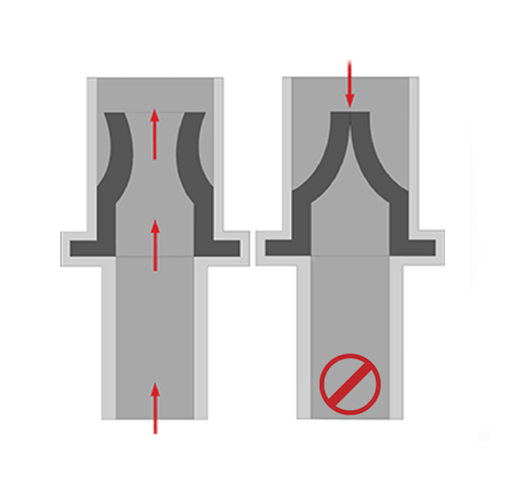
Figure 10: Duckbill check valve with flow orientation arrows.
10. Foot Valve

Figure 11: Foot valve.
A foot valve is simply a check valve type in combination with a strainer on the inlet side that is installed at the end of a section of piping/hosing as their input doesn’t have a connection point. Common check valve types included in a foot valve are in-line spring assisted or an in-line ball check valve, therefore, they only allow flow in one direction and are assisted in closing with a spring. They have a strainer on the inlet side to prevent debris from entering the check valve that could clog or damage something downstream. They are typically installed at the end of a pump suction line of a water well, fuel tank, or any other application where the suction line is situated below the pump. Therefore, they can be used to keep pumps primed, prevent liquid from siphoning back, and keeping debris out of the line.
Related Info
What is Check Valve?4 Common Failure of Piston Pump
Introduction to Priming in Pumps
What is Piston Pump?
