


Video: What Is a Closed Loop System (Servo System / Servomechanism)?

Figure 1: Schematic diagram of closed-loop system and open-loop system.
As shown in the figures above, the closed-loop control system has a feedback device to feedback the position of the servo motor, but the open-loop control system does not.

Figure 2: Schematic diagram of closed-loop system.
The motors in the two pictures above are in a closed-loop system, but the load in the upper picture is in an open-loop system, and the load in the lower picture is in a closed-loop system, because the latter picture has an encoder and a glass ruler for load position feedback.
Simply put, a closed-loop system is one that corrects system errors (position, speed, or torque) by using feedback devices to compare the system's actual performance with its commanded performance.
Therefore, to decide whether it is a closed loop, the key point is to see whether the system has a feedback signal, and use the feedback information to adjust the input to control the output so that it is close to the target value.
Like driving a car, we have a destination and a maximum speed limit. We can control the speed by controlling the accelerator or ignition switch so that it reaches the destination as quickly as possible without exceeding the maximum speed limit.
During this process, we know how far we are from the target and what our real-time speed is. Before reaching the destination, we all want to move forward at full speed, but if the speed exceeds the maximum limit, we slightly release the accelerator or switch to reduce the speed.
Obviously, the speed control here is a closed-loop control.

Figure 3: Simplified control system diagram.
As the above figure shows, closed-loop control systems have feedback, while open-loop control systems do not.
1. Servo System Components
A typical servo system includes motors, controllers, drives, feedback devices and other equipment.
1.1 Servo Controller
The servo controller, also known as the motion controller, can be thought of as the brains of the servo system. Motion curves such as acceleration, speed, etc. are generated here. The controller sends signals to the driver, which causes the motor to perform the desired movement.
The controller also performs the important task in a closed-loop system, correcting errors between actual and desired values, including position, speed, torque, etc.
1.2 Servo Drive
The servo drive, also known as servo amplifier, amplifies the signal from the servo controller to provide the motor with enough current to produce speed and torque. In a rotating motor, the current is directly proportional to the torque, so the servo drive directly controls the torque produced by the motor. Likewise, in a linear servo motor, the current is proportional to the force, so the driver controls the force produced by the motor.
1.3 Feedback Device
The feedback device usually consists of an encoder or resolver (which can be seen as a sensor). In applications that require very precise positioning, two feedback devices can be used, one on the motor to verify the performance of the motor and the other on the load to verify the actual position of the load.
Double loop control is often used for precise positioning of linear axes, with a rotary encoder on the motor and a linear encoder on the linear axis.

Figure 4: Double loop control diagram from ABB.com.
As mentioned above, in a servo motor, the quantities that need to be controlled include position, speed and torque or force.
These quantities can be provided by sensors such as encoders or grating scales, Hall sensors, LVDTs (the torque needs to be detected by a current sensor), and the controller calculates and gives control commands, which are transmitted to the drive. Then the drive drives the motor to operate according to the set displacement, speed or torque.
1.4 Feedback Loop
The current sensor provides a signal of the current flowing through the motor and sends the signal back to the controller, which subtracts the signal from the command signal and acts on the motor. When the servo motor is at the command current, the loop is satisfied. When the current drops below the command current, the loop will increase the current until the command current is reached. The entire loop process is extremely fast, usually updating in the sub-second level.
The speed loop works the same way. The DC motor voltage is proportional to the speed, and when the speed is lower than the command speed, the speed loop sends a command to the current loop to increase the current and thus the voltage.
AC motors can feedback speed and position through encoders and other sensors, and change current through speed loops and position loops to achieve control. The three loops work in sync in an optimized manner to provide smooth and precise control of the servo.
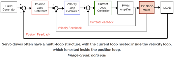
Figure 5: Closed-loop control diagram.
Therefore, whether a motor can be regarded as a servo motor, the most important thing is to see whether it is used in a closed-loop system. The feedback devices can be integrated into the motor, or they can be installed separately from the motor in the system. Sometimes, the servo drive and the servo controller can be integrated into a single device.
2. FAQs about Servo Motor
2.1 What Is a Servo Motor Used For / What Does a Servo Motor Do?
A servo motor is a device that provides precise control of angular or linear position, velocity, and acceleration. The motor's feedback system allows it to adjust and maintain the desired position, making it suitable for tasks requiring accuracy and stability. It is commonly used in various applications, such as robotics, automation, and mechatronics, where precise motion control is essential for tasks like steering, positioning, and maintaining stable movements in response to input signals.

Figure 6: Servo motor used in robotic arms.
2.2 How to Control Servo Motor?
To control a servo motor, you typically use a microcontroller or a dedicated servo motor controller.
1. Connect the servo's power and ground wires to a suitable power source. The control wire goes to a digital output pin on the microcontroller.
2. Use a PWM (Pulse Width Modulation) signal to control the servo's position. Most microcontroller platforms provide libraries or functions to generate PWM signals.
3. Specify the desired angle by adjusting the pulse width within a specific range (usually 1 to 2 milliseconds).
4. The servo will move to the corresponding position.
5. Experiment with pulse widths for precise control.
2.3 Are Servo Motors AC or DC?
Servo motors can be either AC (alternating current) or DC (direct current), depending on the design and application. DC servo motors are common and operate on DC power, while AC servo motors are designed for use with AC power. Both types are widely used in various applications, with DC servos being more prevalent in smaller and less complex systems, and AC servos being utilized in larger industrial applications.
2.4 How to Select Servo Motor
To select a servo motor, consider the following factors:
1. Torque Requirements: Determine the torque needed for your application.
2. Speed Requirements: Assess the speed specifications required for your system.
3. Size and Weight: Choose a motor that fits within your space and weight constraints.
4. Voltage and Power Supply: Ensure compatibility with your power supply.
5. Feedback System: Select an appropriate feedback device (encoder, resolver) for accurate control.
6. Environmental Conditions: Consider factors like temperature, humidity, and exposure to dust or chemicals.
7. Integration: Check compatibility with your control system and ease of integration.
8. Cost: Balance performance requirements with budget constraints.
