


Figure 1: Transformers.
You might have come across various types of Transformers in your daily life either knowingly or unknowingly. Different types of transformers are explained in brief in this article.
1. Power Transformers
Transformers that are used at the generating station to step up generated voltage are normally referred to as power transformers. These transformers are usually rated above 500kVA and are present between the generator and the distribution circuits. These transformers are also known as step-up transformers. Their construction varies with rating and installation locations. For outdoor use, they are usually oil-immersed whereas for power transformers intended for indoor use are primarily dry type.

Figure 2: Outdoor power tranformers.
2. Distribution Transformers
Distribution transformers do the same job of delivering the power to consumers at required voltage levels. These type of transformers are step down transformers – meaning that their function is to reduce the applied voltage to lower levels, to fulfil the requirements of consumers or load centres. Even though industrial standards limit the rating of distribution transformers to 500kVA, even higher ratings are also being manufactured.
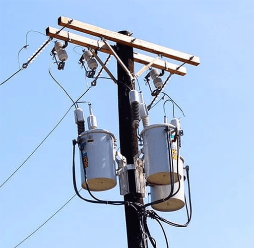
Figure 3: Distribution transformer.
3. Potential Transformers or Voltage Transformers
The potential transformers or voltage transformers are used to step down the system voltage to lower levels so that measuring instrument can be connected. They cannot be used for supplying raw power to the load. They are used with voltmeter, wattmeter, power factor meter, frequency meter, synchroscopes, circuit breaker tripping circuits etc. The primary side of the transformer is connected to the high voltage circuit and the instrument or other circuits are connected to the secondary winding. Any number of instruments can be connected to the secondary unless until the total impedance does not exceed the rated burden of the PT.

Figure 4: Voltage transformer.
4. Current Transformer
As like potential transformers, current transformers or CTs are used to isolate measuring and sensing devices to high current circuits. The primary of a CT is connected in series in the circuit to be monitored and the protection circuits and measurement devices are connected to its secondary. The physical aspects and the connections may vary from one CT to other depending on its type.

Figure 5: Current transformer.
5. Dry Type Transformer
A dry-type transformer is the one which does not contain a liquid medium surrounding its windings. The insulating medium surrounding the winding is a gas or dry compound. When compared to oil-immersed ones, dry-type transformers are lighter and nonflammable. Windings are coated with resin or varnish to protect them from adverse environmental conditions. They are suitable for both indoor and outdoor applications, but they are recommended only for dry environmental conditions. Some of them are equipped with forced cooling arrangements also. They are rated up to 30MVA or 30000kVA. Installation space required by them is much lesser than that of oil-immersed transformers.

Figure 6: Dry type transformer.
6. Oil-immersed Transformers
All power and distribution transformers, except the dry ones are oil-immersed transformers. As discussed earlier, the core and windings on these transformers are completely immersed in oil. The transformer oil provides better insulation and cools the core and winding.

Figure 7: Oil-immersed transformer.
7. Constant Voltage Transformers

Figure 8: Constant voltage transformer.
Constant voltage transformers or CVT are primarily used as noise reduction device. It is a constant voltage output transformer, meaning large variations in input voltages results in very small variation in output voltage. These transformers are based on saturation of ferromagnetic material and ferro-resonance. CVTs are capable of reducing voltage sags and are widely used in dc power supplies, contactors, relays, solenoid valve, switched mode power supplied and PLC (Programmable logic controller) circuits. The output voltage regulation capability of a constant voltage transformer is determined by the inrush and steady operational currents of the connected load. CVTs works are low voltages (max 260V) and are available up to rating of 1500VA.
8. Phase Shifting Transformers

Figure 9: Phase shifting transformer.
Phase shifting transformers (PST) are used to improve the power transfer efficiency of AC networks. A PST creates a phase shift between primary and secondary sides. This phase shift affects the flow of current through the circuit. It is also known as quadrature booster. A quadrature booster consists of two separate transformers. One of them is connected in series to the main circuit and the other is connected across the phases. The output of the shunt transformer is then applied to the input side of series transformer. The magnitude of voltage and phase shift can be controlled by varying the taps on the secondary of shunt connected transformer.
9. Step Voltage Regulator

Figure 10: Step Voltage Regulator.
Maintaining the voltage level within the limit is necessary to maintain power quality. The step voltage regulator is one such device that keeps the magnitude of voltage within the limits. It consists of an autotransformer, a tap changer and control circuit for automatic tap changing. Step regulators can be used in single-phase, three-phase or any one phase of the wye or delta connected three-phase system.
10. Autotransformers

Figure 11: Autotransformer.
An autotransformer is a transformer single winding. It consists of a single winding that acts as both primary winding and secondary winding. The energy transfer between the primary and secondary sides of an autotransformer happens mainly through conduction and a small amount of energy is transferred by induction. Their advantage over the two winding transformers is that for the same VA rating, autotransformers need lesser copper conductors for windings. Also, it has lesser losses and higher efficiency than normal transformers.
Related Info
What is a Transformer?Classification and How Does a Transformer Work?
VFD Types And Applications?
How Does a VFD Work?
