


Figure 1: Semi-hermetic refrigeration compressor.
When the compressor is running, some abnormal situations may occur, such as: the exhaust pressure is too high, the suction pressure is too low, the oil pressure is insufficient, the motor is overheated, and excess liquid enters the cylinder, etc. When an abnormal situation occurs, the compressor will be damaged if there are no protective measures.
The protection measures taken on the compressor can be divided into four types:
●Preventing liquid slugging;
●Pressure protection;
●Protection for built-in motor;
●Temperature protection.
1. Prevent Liquid Slugging
When too much liquid enters the cylinder and can not be discharged from the exhaust valve in time, liquid slugging will occur in the cylinder. The high pressure generated during the liquid slugging will damage the cylinder, piston, connecting rod... and other parts, so a series of protective measures must be taken.
1.1 Oil Heater
The lubricating oil of the crankcase has refrigerant dissolved in it, and the dissolved amount increases when the ambient temperature is low. When the compressor starts, the pressure in the crankcase suddenly drops, a large amount of refrigerant vaporizes, and the lubricating oil is foamed and sucked into the cylinder, causing liquid slugging.
It is an effective measure to avoid liquid slugging by using an oil heater to heat the lubricating oil before starting to reduce the amount of refrigerant dissolved in the lubricating oil.
1.2 Gas-Liquid Separator
The gas-liquid separator, also known as the liquid receiver, mainly protects the compressor by separating and storing the refrigerant liquid in the return pipe.
The gas-liquid mixture from the evaporator is separated in the gas-liquid separator. The separated liquid is accumulated at the bottom of the separator. The liquid refrigerant is vaporized by heat and enters the upper part of the outlet pipe, and the lubricating oil that cannot be vaporized flows into the compressor from the return hole.
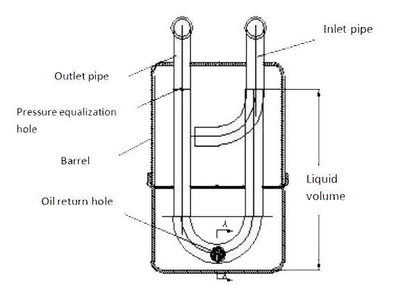
Figure 2: Structure diagram of gas-liquid separator.
2. Pressure Protection
2.1 Suction and Exhaust Pressure Controls
When the compressor is running, due to the reasons of the system or the compressor itself, the discharge pressure may be too high or the suction pressure may be too low, so the suction and discharge pressure must be controlled.
Common controllers are high and low pressure pressure controllers, which consist of a high pressure control part and a low pressure control part.
When the exhaust pressure exceeds the given value, the high pressure control part will act to cut off the power supply of the compressor and make it stop.
When the suction pressure is lower than the given value, the low-pressure control part will operate to cut off the power supply of the compressor to stop it.

Figure 3: Air -conditioning unit/heat pump working principle diagram.
2.2 Oil Differential Pressure Controller
During the operation of the refrigeration compressor, its moving parts need lubricating oil with a certain pressure for constant lubrication and cooling. In order to ensure the safe operation of the compressor, the oil pressure must be controlled.
When the oil pressure drops not enough to make the compressor work safely, and does not recover above the set oil pressure value during the delay setting period, the main circuit will be cut off, and the compressor will stop working, so as to protect the compressor from damage.

Figure 4: Installation diagram of oil differential pressure control in refrigeration system.
1. Differential pressure control 2. Oil pressure gauge 3. Oil pump 4. Compressor
3. Protection for Built-in Motor
3.1 Overheating Relay
A motor that is well designed and operated under specified conditions will not have an internal temperature that exceeds the allowable value. However, when the motor is running at too high or too low voltage, or in a high temperature environment, the internal temperature of the motor will exceed the allowable value. When it is started frequently, the temperature of the motor will be too high due to excessive starting current.
In order to prevent the motor from overheating, in addition to correct use and maintenance, an overheating relay can also be installed. The overheating relay can be installed inside the winding, called a built-in temperature relay, or installed outside the motor, called an external temperature protector.
3.2 Overload Relay
A phase loss of a three-phase motor will cause the motor to fail to start or be overloaded. To protect the motor from phase loss, an overload relay is required. Overload relays are also used in normal three-phase motors to protect the motor when the current is too high.
Unbalanced voltage between phases causes unbalanced current in three phases. In the phase with the largest current, the temperature rise increases approximately twice the square of the voltage unbalance ratio. For example: 3% voltage unbalance produces about 18% temperature rise. The measures to protect the motor from unbalanced phases are the same as that for phase loss.

Figure 5: Schneider thermal overload relay.
4. Temperature Protection
4.1 Thermostat
Excessive exhaust temperature leads to the decomposition of refrigerant, the aging of insulating materials, carbonation of lubricating oil, damage to gas valves, and blockage of capillary tubes and filter driers. The protection method is to use the thermostat to sense the exhaust temperature.
The thermostat should be installed close to the exhaust port. When the exhaust temperature is too high, the thermostat will act and cut off the circuit.
If the excessive exhaust temperature is caused by the bypass of hot gas, the method of shutting down should not be used, but liquid spray cooling should be used.
4.2 Case Temperature Protector
Case temperature will affect the life of the compressor. Excessive casing temperature may be caused by insufficient heat exchange capacity of the condenser, so the fan of the condenser should be checked.
If air or other non-condensable gases enter the refrigeration system, the condensation pressure will rise and the casing will overheat. If the suction temperature is too high, the casing will easily overheat. In addition, an overheated motor can overheat the enclosure.
The fundamental way to avoid overheating of the casing and protect the compressor is to correctly deal with the above-mentioned problems. At the same time, a temperature protector should be installed on the casing.
The most commonly used casing temperature protector is placed in a suitable place on the casing. When the temperature of the casing is too high, the dish-shaped bimetal will deform after sensing the rising temperature, causing the contacts in the circuit to disconnect and the compressor to stop.

Figure 6: Hanbell compressor protection module.
4.3 Oil Temperature Protection Device
Prevent the temperature of lubricating oil from being too high. During the operation of the compressor, sometimes although the oil pressure difference is normal, the oil temperature may be too high and the lubricating performance may decrease, causing the friction parts to be burned out. Therefore, the oil temperature must be controlled.
Conclusion
The aforementioned protection devices are part of the protection and control devices of the compressor. In addition, there are liquid level protection and control, medium pressure protection and control, and safety valves. These protective measures may not all be used in actual projects, but should be determined according to specific conditions.
As we all know, the Copeland compressor is very sturdy and durable. First of all, it must benefit from the design, material selection and reasonable assembly structure of the Copeland compressor components, but more importantly, the numerous protection modules/devices installed inside the compressor.
Related Info
15 Refrigeration System Components Structure, Function, Working Principle Diagram (1)15 Refrigeration System Components Structure, Function, Working Principle Diagram (2)
14 Common Ice Maker Problems and How to Fix Them
How a Refrigeration Compressor Works
How to Tell if Refrigerator Compressor is Bad
