


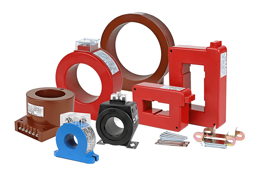
Figure 1: Current transformers.
The CT (Current Transformer) is a component used to detect current signals, which is based on a transformer. Compared with Hall devices, it is cheaper, but due to the exciting current, the detected current will be wrong in principle. But for the applications that do not require high-accuracy current, a current transformer can play an important role. This article will introduce the use, the model, the method to avoid saturating and its selection.
Use of Current Transformers
It’s a Buck topology, and the CT is used for peak current signal detection on the input side.

Figure 2: The schematic diagram of peak current detection.
The reference signal of peak current is given through the control loop (outer), and the instantaneous information of current(VR) is obtained by the CT, which is sent to the rear comparator to give the turn off signal of S1. So the CT is to convert the input current into a voltage signal. Introduction to the connection method of the secondary side winding will be explained later in the article.
Current Transformer Model
Because the CT is basically a transformer, and the equivalent model of the transformer is shown in figure 3.
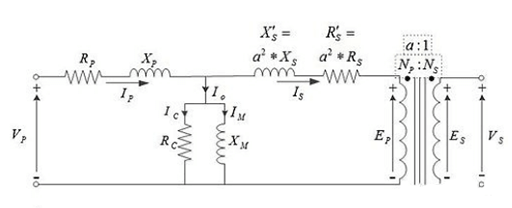
Figure 3: An equivalent model of the transformer.
Seeing from the figure, we will find that the left side is the T model, and the right side is the ideal transformer. RP and XP are the resistance and the leakage inductance of the primary side. XS’ and RS’ are the impedances converted from the secondary side to the primary side. RC and XM belong to excitation impedance.
The model is much more complicated for us to analyze. In fact, the values of leakage inductance and parasitic resistance are relatively small compared with the exciting resistance and inductance, while RC is extremely larger than XM. Therefore, we can simplify the model as figure 4.
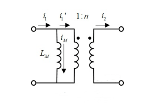
Figure 4: A simplified model of transformer.
In the simplified model, only the LM corresponding to exciting inductance and the ideal transformer are retained.
i1’ = n * i2
We want i1 = n * i2, or approximately equal so as to detect the current. So how can we eliminate the IM from the diagram? What conditions should be satisfied?
Since i1 = i1’+ iM, as long as iM is infinitely small, the current of the exciting inductance can be ignored. Therefore, the exciting inductance is generally designed to be large enough to achieve signal conversion.
On the other hand, the inductance would be saturated. If the exciting current is extremely large, the inductance magnetic core will be saturated, LM will become smaller, and iM relative to i1’will no longer be ignored. And the current of the secondary side of CT will not satisfy i1 ≈ n * i2, leading to the detection signal distortion. In addition, a large part of i1 will flow through the magnetic inductance, causing the transformer to heat up or even burn down.
How to Avoid CT Saturation
Since the magnetic inductance is equivalent on the primary side or the secondary side (with a difference of a ratio coefficient), the signal extraction is on the secondary side. So we convert the magnetic inductance to the secondary side.

Figure 5: The simplified equivalent model of the CT.
The volt-second balance of magnetic inductance is helpful to prevent it from saturation. The integral of the positive voltage over time in one cycle should be equal to that of the negative voltage. Therefore, there must be both positive and negative voltage on the magnetic inductance during one switching cycle. Considering that a detecting signal needs to convert the current signal to the voltage signal, the simplest way is to use the resistor.
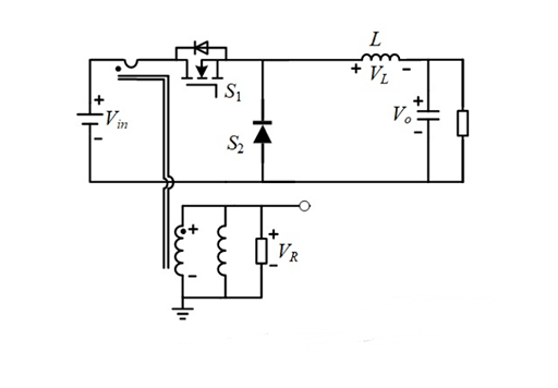
Figure 6: A circuit that uses the resistor to convert the current signal to the voltage signal.
When switch S1 is turned on, the input current signal will generate a voltage VR on the impedance of the secondary winding of CT, the voltage on LM is VR. When switch S1 is turned off, the current of the magnetic inductance cannot change abruptly and continues through the resistor R, so the voltage on LM is -VR.
As a result, there are both positive and negative voltages on the magnetic inductance. But if the D(duty cycle) > 0.5, the magnetic inductance will not satisfy the volt-second balance during one switching cycle. So a larger negative voltage is required, using the following circuit.
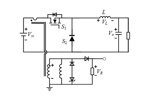
Figure 7: A circuit with larger negative voltage uses the resistor.
When switch S1 is turned off, the current continues to flow through the voltage-regulator tube, which provides a relatively large clamping voltage, thus ensuring the volt-second balance. At the same time, VR can also be used as a peak current signal.
Current Transformer Selection
Here are parameters of the CT manufactured by Coilcraft.
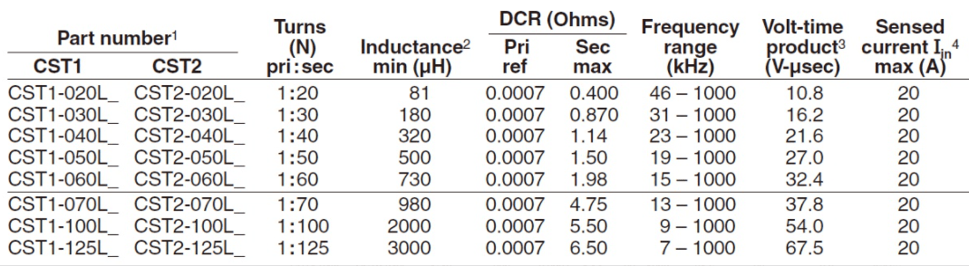
Table 1: Main parameters of current transformers of the CST series manufactured by Coilcraft.
* Main parameters
Turns(N)
It is the turn ratio, based on the actual required current conversion ratio to choose the appropriate CT.
Inductance
It refers to the magnetic Inductance. Higher Inductance is preferred (low exciting current), but the higher Inductance means larger volume.
DCR
Direct current resistance. The DCR is explained as the winding resistance.
Frequency range
Switching frequency range.
Volt-time product
The voltage-regulator tube can construct negative pressure to ensure the volt-second balance, but if the switching frequency is extremely low and the duty cycle is excessive, CT may be saturated on the positive voltage within one cycle.
Sensed current Max
The maximum current that can be detected.
Summary
This article has introduced the CT’s use, model, saturation solutions, and selection. I hope these will help you in your application of a current transformer.
