


As is known, the reciprocating compressor’s piston rod connects the crosshead to the piston. What if piston rods fail?
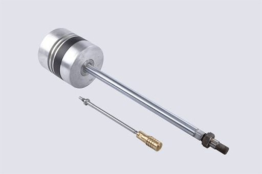
Figure 1: A piston rod for a reciprocating compressor.
We will tell you factors affecting piston rods by an example. For instance, a compressor is a two-row symmetrical balance type. It is a horizontal reciprocating compressor, with two stages. Its cylinder is water-cooled with less oil lubrication.
Technical Specifications
Exhaust capacity (air sucked into the inlet): 5.25m3 /min
Suction pressure: 2.35/5.1 MPaG
Exhaust pressure: 5.1/10.8 MPaG
Suction gas temperature: 40/40 °C
Exhaust gas temperature: 119/117 °C
Lubricating oil pressure: 0.35 - 0.4MPAG
Compressor speed: 372 r/min
Piston stroke: 280 mm.
Cylinder diameter: Φ220/160 mm
Shaft power: 445 KW
Media: Hydrogen, methane, etc
Structural Characteristics of Compressor Components
Reciprocating Compressor Piston & Piston Rod
The piston rod material of the first stage is 17-4PH. The second-stage piston and piston rod are an integral structure, whose material is 17-4PH. The surface of the friction part between the piston rod and packing is treated with tungsten carbide, whose hardness is greater than HRC65. The piston is connected to the piston rod by a super nut, in which a single screw is rated as a fastening torque of 49N.M.
Reciprocating Compressor Crosshead
The cross head is a combination structure with two sides of the cylinder type. The cross head body as well as the upper and lower detachable sliding shoe are positioned by wedge groove and connected into a whole with the help of screws. There is an adjusting gasket between the slipper and the cross and, as a result, the sides of the cross head lateral force in the opposite direction.
To ensure the concentric run of the cross head and piston rod, the factory has adjusted the quantity of gaskets between the cross head and slipper which are forced opposite. So when users install and maintain the compressor, they should not change the cross head or increase and decrease gaskets.
The cross head is made of ZG230-450. The material of the upper and lower sliding shoe is No.20 steel. The bearing alloy is hung on the pressure bearing surface and the oil grooves facilitate the distribution of the lubricating oil. The cross head pin is a direct type, fixed in the cross head pin hole, and the shaft and radial oil holes are distributed in the pin for lubricating oil transportation. The hydraulic connecting fastening device is used for the connection between the piston rod and the cross head body, which is mainly composed of the connecting device and the fastening device.
* Working principle
By connecting the fastening device, you can connect the piston rod and cross head. Using the manual ultra-high pressure oil pump, you can inject oil of 150 MPa to the pressure body of the fastening device, and use the incompressible liquid to drive ring piston, forcing the piston rod end to be deformed, and then lock the nut and depressurize the oil. The preload required for the connection can be achieved.
The pressure of the oil pump should not exceed 150 MPa. The whole process of fastening should be completed after three times of operations, and each time with an interval of 1 hour. The method of fastening is the same for each time.

Figure 2: Reciprocating compressor cross head.
Inspections
Clearance at the outside dead centre of the 2-stage piston of the compressor was 0.60mm. The connection between the piston rod and the cross head was confirmed to be loose through the data. It was preliminary judged that the piston had not hit the cylinder in the process of idle operation during the shutdown.
At the 2-stage packing, the piston rod jumped at the radial direction with 0.01mm horizontally and 0.02mm vertically. The preliminary judgment was that the piston rod had not been subjected to excessive axial compression deformation.
The 2-stage piston rod was connected with the cross head by the hydraulic nut, and the locking nut has become loose because of the reciprocating inertia and vibration during operation, leading to the impact of nut and pressure body thread. It resulted in thread fracture slip buckle, so the cross head could not be removed in accordance with the normal method.
The connecting flange bolts of the compressor’s two stages of cylinders and the middle body were checked. They checked the connecting flange bolts of the middle body and the crankcase. There was no obvious loosening phenomenon, which further showed that the piston had not collided with the cylinder.
The 1-stage piston rod and the cross head were connected with the hydraulic tightening nut, which was not abnormal.
After checking the connecting nut between the piston rod and cross head, they found that there was no wear and fracture; removed the piston rod, and checked the piston and piston rod, cross head internal thread, no damage, and finally confirmed that the piston did not impact with the cylinder head.
Then the workers cleaned up the debris of the cross head slide, repaired the parts where the cross head plane was knocked against by the hydraulic nut, ground the matching surface of each part to achieve the conditions of reloading. After reloading, it was tested without load for 1 hour, and there was no abnormality.
Cause Analysis
The following will analyze installation specifications and technical requirements of hydraulic nut connecting piston rod and cross head.

Figure 3: Reciprocating compressor components, including valves, a piston rod, oil wiper rings, crankshaft, frame, crosshead, connecting rod, rod packings, and piston.
Details of Hydraulic Nut Installation & Adjustment
Assemble the pressure body, sealing ring, annular piston and lock nut into the end of the piston rod and the shoulder of the piston rod, and return the lock nut to the position flush with the annular piston.
Screw the regulating ring into the inner nut, so that the radial hole is aligned with any screw hole of the inner nut, and screw the screw into the end of the piston rod.
The thrust ring is installed on the outer end of the piston rod, and the tension spring is used.
Turn the cross head to move the piston rod and introduce the end of the piston rod into the cross head neck. Use a rod wrench to turn the adjustment ring to screw the inner nut into the cross head threaded hole until the adjustment ring contacts the end face of the cross head neck, and then tighten the locking nut to the end face of the neck of the cross head. During the process, the piston should be prevented from rotating.
Rotate the compressor. Respectively measure clearance between the front and rear dead stops of the piston with the lead pressure method.
If the clearance difference is large, you should unscrew the lock nut and turn the positioning screw, remove the positioning screw on the coil, adjust the adjustment ring according to the need. Then you should repeatedly tighten the locating coil and the locking nut, and measure the piston check point gap. You could adjust it until the clearance of dead points meets the requirements.
After the clearance between the front and rear dead stops of the piston is qualified, the locking nut should be removed. You should remove the screws on the positioning screw ring, and apply the anaerobic glue, and then screw the locking nut.
Hydraulic Fastening Steps
Connect the hose of the manual ultra-high pressure oil pump with the G1/4 interface on the pressure body.
Lift the handle of the oil pump to make the pressure rise to 150MPa (maximum). Under the oil pressure, the annular piston and the pressure body press to the shoulder of the positioning screw and the piston rod respectively, forcing the end of the piston rod to elastic elongation deformation.

Figure 4: The piston rod is deformed.
At this time, the locking nut is separated from the cross head’s neck, and the locking nut is tightened again with the rod wrench. When fastening, you can use a small hammer to gently knock the rod wrench to ensure that the locking nut and the end face of the cross head’s neck contact tightly. And after the pressure relief, the first hydraulic fastening is completed.
After the completion of the first hydraulic fastening, the end of the piston rod should be kept in the initial elongation state for 1 hour, and then you should tighten it again. The same method as the first time was carried out at the pressure of 150MPa.
After the completion of the second hydraulic fastening, the piston rod is kept in the continuous elongation state for 1 hour, and then the third hydraulic fastening. The same method as the first time was carried out at the pressure of 150MPa. After pressure relief, hydraulic fastening work is completed, and you can put it into use.
Analysis of Main Causes
Hydraulic lock nut is a high-precision part with fine thread and spin, so frequent disassembling may cause minor knocks against. If the worker does not check it carefully, there will be a problem that it is cracked down to the specified value, but the confined area is small, and the vibration causes the loose in the operation. And the pressure body has the rubber sealing ring, which would be aging.
For the pressure gauge of the tightened manual pressure pump, there are two laps of MPA and PSI scale, which may cause identification misreading, leading to pressure without reaching the specified value.
The suppression is not meeting the requirements of provisions for three times, and each interval is 1 hour by aging treatment, resulting in the extension of the piston rod failing to reach the set value.
Combined with the site situation, the reasons that may cause the loosening of the hydraulic nut are sorted out:
The hydraulic nut assembly before installation has been cleaned and checked thoroughly, and there is no burr.
The maintenance personnel only pressed the nut for two times with each interval of 30 minutes, which is not in accordance with the technical specification requirements. This is the main reason for the loosening of the hydraulic nut.
In order to verify the influence of hydraulic nut pressing for three times on the piston rod extending, when changing new components of the hydraulic nut, magnetic seat dial meter is used to monitor the extended length of piston rod end and the statistics of aging treatment time are as follows:
|
No. |
Pressure |
Piston rod elongation |
Treatment |
|
1 |
150MPa |
0.85mm |
60 minutes |
|
2 |
150MPa |
0.08mm |
60 minutes |
|
3 |
150MPa |
0.02mm |
60 minutes |
Table 1: Extended length of piston rod at three times of pressuring.
Conclusion
It can be seen from the on-site pressure statistics that the lack of pressure times and the insufficient aging treatment have a significant impact on the connection loosening. And it finally determined that the maintenance operation is not following the technical requirements of the construction without enough pressure times and the time of aging treatment. That is the cause of the compressor failure. Learning from this failure, maintenance workers will realize the importance of key quality points strictly complying with the technical requirements.
Related Info
Reciprocating Compressor Bearing Bush TroubleshootingAC Compressor Bearing - Working Principle & Troubleshooting
List of Problems and Solutions for Piston Compressors
