


In modern construction machinery, hydraulic working devices are basically inseparable. Even if the main working device does not use hydraulic equipment, it usually also needs hydraulic systems to achieve some auxiliary work. When it comes to the hydraulic system, we must mention the pump. The birth of the pump is very early. The ancient equipment used to lift water is the earliest pump, such as the waterwheel in China and the chain pump in Egypt.
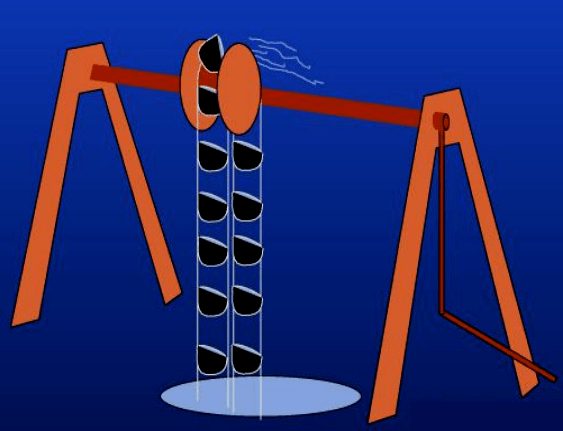
Figure 1: Egyptian chain pump diagram.
Hydraulic transmission is widely used in various fields and is called "the muscle of industry". In hydraulic transmission, the hydraulic pump is the power element and the "source" of its power. Especially in the era of mechanization, it is everywhere, and its importance is self-evident.
1. Introduction to Hydraulic System
1.1 The Composition of the Hydraulic System
A complete hydraulic system consists of five parts, namely power components (hydraulic pump), actuators, control elements, auxiliary components and hydraulic oil.
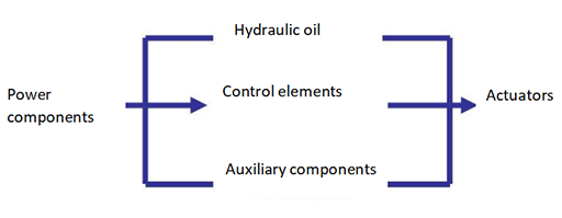
Figure 2: The composition diagram of the hydraulic system.
The function of the actuators (hydraulic cylinder and hydraulic motor) is to convert the pressure energy of the liquid into mechanical energy, and drive the machine to perform linear reciprocating motion or rotary motion.
Control elements (various hydraulic valves) control and regulate the pressure, flow and direction of liquids in hydraulic systems.
Auxiliary components include oil tank, oil filter, sealing ring, pressure gauge, etc. Hydraulic oil is the medium that transmits energy in the hydraulic system, including mineral oil, synthetic hydraulic oil, etc.
The function of the hydraulic pump is to convert the mechanical energy of the power machine (such as an electric motor or an internal combustion engine) into the pressure energy of the liquid. That the output flow can be adjusted according to the needs is called variable pump, while that the flow can not be adjusted is called quantitative pump.
Although the structures of different types of hydraulic pumps are quite different, there are many commonalities in installation, use and maintenance, and failures may occur if they are not operated properly.
1.2 The Working Process of the Hydraulic System
First, the motor drives the oil pump to rotate. After the hydraulic pump sucks oil from the oil tank, it converts the mechanical energy into the pressure energy of the hydraulic oil. The direction of the hydraulic oil is controlled by the integrated block (or valve group) and the hydraulic valve. They pass the hydraulic oil to the oil cylinder or oil motor of the hydraulic machine through the external pipeline, control the direction conversion, strength and speed of the hydraulic machine, and then push it to work.
Hydraulic station, also known as hydraulic pump station, is an independent hydraulic device consisting of pump device, integrated block or valve, fuel tank and electrical box. It supplies oil according to the requirements of the driving device (main unit), and controls the direction, pressure and flow of oil flow. It is suitable for various hydraulic machines where the main engine and the hydraulic device are separated.
After purchase, as long as the hydraulic station and the actuators (oil cylinder and oil motor) on the main engine are connected with oil pipes, the hydraulic machine can perform various specified operations.
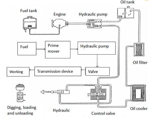
Figure 3: Structure and hydraulic operating system of single bucket excavator.
2. How Hydraulic Pumps Work?
According to the pump structure commonly used in the hydraulic system, the hydraulic pump is divided into three types: gear pump, vane pump and piston pump. The following describes the working principles of these three types of hydraulic pumps.
2.1 Working Principle of Hydraulic Gear Pump
The hydraulic gear pump has the characteristics of small size, simple structure, strong anti-pollution, low price, large leakage, large noise, large flow pulsation, and unadjustable displacement.
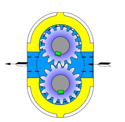
Figure 4: External gear pump diagram.
A hydraulic gear pump consists of two gears that engage with each other. When the motor or engine drives one of the gears, the other gear that engages with it will rotate at the same time. The pair of gears rotate with each other, the gear teeth on one side of the meshing teeth gradually disengage, and the volume of the sealed cavity increases, forming a partial vacuum.
The hydraulic oil in the tank is sucked in under the action of atmospheric pressure to fill the increasing volume. The hydraulic oil sucked in fills the tooth slots and the oil is brought to the pressure oil chamber on the other side of the meshing area as the tooth slots rotate.
The meshing of two gears separate the oil suction chamber and the pressure oil chamber, so that there will be no hydraulic oil leakage between the oil suction area and the pressure oil area. The gears rotate continuously to complete the process of oil suction and pressure oil again and again.
2.2 Working Principle of Hydraulic Vane Pump
The hydraulic vane pump has the characteristics of uniform flow, stable operation, low noise, high working pressure and volumetric efficiency, and complex structure.

Figure 5: Sing acting vane pump diagram.
A hydraulic vane pump is an eccentric structure formed by the rotor and the vanes. As the rotor rotates under the drive of the drive shaft, the lower end of the vanes always maintains sufficient pressure because of the action of the spring or hydraulic oil, so that the top of the vanes can be close to the inner wall of the pump.
During the rotation process, a closed space is formed among any two adjacent vanes and the pump body. When the closed space gradually becomes larger, the hydraulic oil is sucked into it. When the volume of the closed space changes from large to small, the hydraulic oil inside is pressed out.
2.3 Working Principle of Hydraulic Piston Pump
The hydraulic piston pump has high volumetric efficiency, small leakage, and can work under high pressure. Most of them are used in high-power hydraulic systems, but they are complex in structure, expensive in price, and require high materials and machining accuracy, and high oil cleanliness.

Figure 6: Structure diagram of piston pump.
The hydraulic piston pump has a drive shaft, which is connected with the cylinder body. The pistons are evenly distributed in the cylinder body along the circumference. One end of the pistons is pressed on the fixed swash plate, and the other end of them is equipped with compression springs. The swash plate has an inclination angle relative to the axis of the pump body, and the pistons will always be pressed on the inclined plate.
When the hydraulic piston pump is working, under the action of the cam on the camshaft of the oil injection pump and the piston springs, the pistons are forced to reciprocate up and down, so as to complete the oil pumping task.
The oil pumping process can be divided into two stages: the oil intake process and the oil return process. The sealing volume between the pistons on one side of the cylinder and the cylinder body gradually increases to become the oil suction area, and the other side is the pressure oil area as the surrounding sealing volume gradually reduces.
3. Precautions for the Use of Hydraulic Pumps
1. When starting the hydraulic pump, jog it several times. After the oil flow direction and sound are normal, run it under low pressure for 5 to 10 minutes, and then put it into normal operation. Before starting the piston pump, fill the pump with clean working oil through the drain port on the casing.

Figure 7: DENISON hydraulic pump.
2. The viscosity of the oil is affected by the temperature. As the oil temperature increases, the viscosity of the oil decreases, so the oil temperature is required to be kept below 60 °C. In order to make the hydraulic pump work stably at different working temperatures, the selected oil should have the oil temperature characteristic of the viscosity being less affected by temperature changes and have good chemical stability, and anti-foaming properties.
3. The oil must be clean, not mixed with mechanical impurities and corrosive substances. An oil filter truck (filtering accuracy less than 25μm) is needed to add oil to the oil tank when the hydraulic system without a filter device on the oil suction line.
4. The maximum pressure and maximum speed of the hydraulic pump, refers to the peak values allowed in use for a short period of time, not for long-term use.
5. The normal working oil temperature of the hydraulic pump is 15-65℃. The maximum temperature on the pump casing is generally 10-20℃ higher than the oil temperature at the pump inlet in the fuel tank. When the oil temperature in the fuel tank reaches 65℃, the maximum temperature of the pump casing should not exceed 75 ~ 85 ℃.
Related Info
FAQs on Hydraulic MotorHydraulic Piston Motor: Types, Working Principle and Pros and Cons (1)
Hydraulic Piston Motor: Types, Working Principle and Pros and Cons (2)
What is Hydraulic Pump? (Function, Types, Application&Selection Method)
Hydraulic Pumps:Types and Pros & Cons
