


The wiring and installation of rotary encoders should be conducted in strict accordance with the instructions of each product. While for general encoder installation guidelines, you should pay attention to the following aspects during your encoder mounting work.

Figure 1: Romuon incremental encoder A2-CW5C installed on an equipment.
1. Installation of Different Types of Encoders
1.1 Solid Shaft Encoder
For solid shaft encoders, you need to pay attention to synchronous flange and clamping flange, which are different on the mounting bracket.
Here are 3 methods of fastening solid shaft encoders.
*Use the mounting hole on the end face of encoder flange directly to fasten the encoder and mounting brackets.
*Use the mounting boss of clamping flange to fasten encoder and mounting brackets by clamp.
*Use the clamping groove of synchronous flange to fasten encoder and mounting bracket by eccentric clamp.
1.2 Incremental Encoder
For incremental encoders, setting zero position through shaft or shaft sleeve and mark on flange will benefit the location assembly and use of the encoder. The fixed hole of the shaft sleeve on the through hole / blind hole hollow shaft encoder corresponds to the zero mark position, which is the mechanical zero position, on the flange surface.
The plat of the solid axis encoder shaft, in which the center line is aligned with the zero mark position on the flange, which is the mechanical zero position.
* About Couplings
*Keep the original state without any distortion when installing the coupling;
*The torque of the top screw on the coupling is generally 0.6Nm. Excessive torque will cause screw damage;
*The encoder and coupling shall be installed in concentric position. Any deviation may cause the mechanical load on the encoder shaft to exceed the rated range.
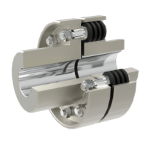
Figure 2: 3D model of cutaway structure of encoder couplings.
1.3 Hollow Shaft Encoder with Blind Hole
For hollow shaft encoder with blind hole, whether it is incremental or absolute encoder, note whether the length of shaft matches the depth of shaft sleeve. For example, dbs60, generally, the length of shaft shall not be less than 15mm and not more than 40mm. And atm60_ SSI, generally, requires that the length of the shaft is not less than 15mm and not more than 30mm.
1.4 Hollow Shaft Encoder with Through Hole
For hollow shaft encoder with through hole, if it’s incremental encoder, you can choose clamping ring and installation reed on the same side or different side. That is determined by the installation environment on site. Note whether it is more convenient to fix the clamping ring after the reed is fixed.
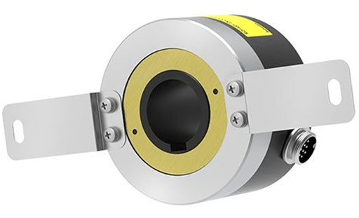
Figure 3: Sample of hollow shaft encoder with through hole, Autonics rotary encoder E100H35-10000-3-T-24
1.5 Installation of Absolute Encoders
The forms of mechanical installation of absolute rotary encoder includes high-speed end installation, low-speed end installation, and auxiliary mechanical device installation.
* Installation in the Low Speed End
Encoders are installed behind the reduction gear, such as the shaft end of the winch steel wire rope drum or the end of the last reducer gear. With this method, there is no gear to return clearance, and the measurement is more direct and the accuracy is higher.
You can use this method to measure long distance positioning, such as various lifting equipment and feeding trolley positioning.
* Installation in the High Speed End
Rotary encoders are installed at the rotating shaft end of power motor (or gear connection). The advantage of this method is that it’s of high resolution. Because there are 4096 cycles of multi-turn encoder, the number of rotation rings of motor can be fully used to improve the resolution with sufficient range within the range.
The disadvantage is that the moving object with gear clearance error after reducing gear is generally used for one-way high-precision control and positioning, such as roll gap control of steel rolling.
In addition, if the encoder is directly installed at the high-speed end, the motor must vibrate slightly, otherwise it is easy to damage the encoder.
* Auxiliary Machinery Installation
This method is commonly used in gear rack, chain belt, friction runner, and rope receiving machinery.

Figure 4: Fastening brackets for Omron incremental rotary encoders E6B2
2. Possible Problems When Installing Incremental Encoders
2.1 Ignoring the Installation of Cabinet
As is known to all technicians, it is very easy to ignore the installation of the cabinet in the process of the installation of precision instruments. Choosing authoritative dealers who will pay attention to the overall details and wiring. The cabinet’s stable state must be ensured during the installation process.
2.2 Ignoring the Whole
People usually pays attention to the subsystem carefully during the installation process, which may result in the neglect of the overall sensory acceptance. So it may lead that some wiring is not beautiful, information panel is irregular. Therefore, we should grasp the whole during the installation.
2.3 Wire Laying
It is necessary to lay wires correctly in installation and connection. The space between wires should be set to be less than the specified standard. If cross laying occurs, it is better to make the space between two wires keep within the specified standards.
During the laying of wires, there is preferably a certain distance from the wall. This distance is called safe distance by technicians, and PVC protection can be taken for the line when necessary. Besides, selecting qualified technicians is very important.

Figure 5: Wiring diagram of rotary encoders
3. Matters Needing Attention When Installing Single-Turn Absolute Encoders
Single-turn absolute encoders measure each channel of the photoelectric code disk in rotation to obtain the unique code. When the rotation exceeds 360 degrees, the coding returns to the original point, which does not conform to the principle of absolute coding uniqueness. Such coding can only be used for measurement within 360 degrees of rotation, which is called single-turn absolute encoder.
The following points should be paid attention to during the installation of single circle absolute encoder:
*The encoder shaft and motor shaft shall be as concentric as possible.
*The connection between encoder cable and extension cable should be welded as far as possible, in order to prevent poor contact caused by long-time oxidation, which will affect the signal acquisition.
*The encoder cable is separated from connecting cables of high-power equipment, frequency converter and other equipment to prevent interference. After the collected gray code is converted into ordinary binary code, it can be corresponding to the actual position / angle value according to the conventional method.
*It is better to select elastic coupling which can significantly improve the eccentric problem caused by poor installation accuracy or abrasion.
*The encoder cable shall be of high-quality shielded twisted copper cable, which can reduce external interference and reduce signal attenuation.
The rule of converting binary gray code into natural binary code is to keep the highest bit of gray code as the highest bit of natural binary code. The second highest bit natural binary code is the high bit natural binary code, which is different from the second high bit gray code. The other bits of natural binary code are similar to the second high bit natural binary code.

Figure 6: Kuebler single-turn absolute encoder 05.2400.1112.0020
4. Procedures for Installing Rotary Encoders
Avoid loosening due to vibration during use.
When connecting encoder, please confirm that the load cannot exceed its maximum allowable value and deviation.
Lock the screw around the encoder coupling shaft to avoid loosening during use.
4.1 Environment
Pay attention to whether there are interference sources around. Encoder is a type of precise instrument which is easy to be disturbed. If it is affected, it will also cause adverse effects on the normal use. Temperature and humidity also need to be concerned, and understand the scope of equipment requirements.
4.2 Axle Load
When installing the rotary encoder, you also need to pay attention to its shaft load and know its allowable range clearly. When connecting the signal line, it must not be connected to DC power or AC power, which will damage the output circuit.
4.3 Connection
In connection, the operator should avoid rigid connection with the encoder but take the plate spring. At the same time, during the installation work, the encoder should be pushed into the quilted shaft gently. The encoder must not be knocked, which will damage the encoder and affect the shafting.

Figure 7: Two rotary encoders installed on a circuit board.
5. Installation of Servo Motor Encoders
In the installation of servo motor encoders, we may encounter various problems, including mechanical and electrical aspects. If the problems are not properly avoided or solved, they will affect the normal use and life of encoders.
5.1 Electrical Interface
The baud rate and transmission distance of electrical interface can be selected according to the specific application environment on site. The actual transmission distance and transmission rate, installation of the encoder and communication cable are affected by environment, grounding and cable material.
5.2 Component Layout
When the encoder is installed on site, it cannot be installed with high-speed interference source equipment such as frequency converter, transformer and solenoid valve. Besides, keep a distance of 10cm, or install metal partition. When installing the module communicating with the encoder, it is not allowed to install with high interference source elements such as frequency converter and contactor or frequently disconnected switch element. In addition, keep a distance of 3cm, or install metal partition.
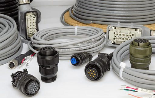
Figure 8: Encoder cables and concators.
5.3 Grounding Protection
The shielding layer of the cable shall be grounded at the signal receiving end in order to prevent the leakage current between the two grounding points from damaging the cable. If the shielding wire of the cable can not achieve good grounding protection, a separate grounding wire should be connected for shielding.
For long-distance grounding connection, yellow and green wires need to be added between the product shell and the grounding point as the equipotential compensation line. The shielded cable must be connected to the metal shell (encoder or electric cabinet) of the electrical components at both ends, and you should also ensure the correct connection.
