


Figure 1: Transmitters are used in petroleum product facilities.
The new type of anti-vibration pneumatic pressure transmitter is used with the BOP (blowout preventer) and the throttle manifold control box for oil and petroleum products. It can convert the high pressure into low pressure in the pipeline, which is helpful in long-distance transmission and control.
Pneumatic pressure transmitters mainly support the use of petroleum machinery products, including BOP ground control devices and throttle manifold control boxes. BOP ground control device is used to control the opening and closing of the BOP assembly with the wellhead and blowout valve when drilling oil or gas well to prevent blowout incidents in well operation. It is one of the important devices indispensable to ensure safety.
The transmitter can also be used for throttle manifold control. It converts the mud pressure in the casing and riser to low pressure and represents the high mud pressure by the low pressure for long-distance transmission and control.
New Type of Pneumatic Pressure Transmitter Working Principle
The transmitter is composed of the piston assembly, regulating valve assembly, diaphragm assembly, and housing. It is designed based on the principle of force balance, that is, the oil pressure (or mud pressure) acting on the piston rod (upward force) and the output air pressure acting on the diaphragm assembly (downward force) is equal.

Figure 2: The regulating valve assembly.

Figure 3: The piston assembly.
The transmitter is driven by supply air. When the air pressure enters the input gas chamber, if there is no measured pressure signal, the valve needle in the regulating valve assembly is not opened so that the supply air is closed in the input gas chamber. At this time, the output gas chamber is in communication with the atmosphere, and the pressure is zero.
If you add a measured pressure signal from the piston gasket set, the deformation of which would cause the piston rod to push the diaphragm assembly upward. The vent nozzle is closed firstly so that the output chamber and the atmosphere partition. And then the diaphragm assembly continues to move up, the valve needle will be opened in the regulating valve.
The fluid in the input chamber flows into the output chamber to form the output pressure, which pushes the diaphragm assembly downward to overcome the upward push from the piston rod. The pressure of the output chamber represents the output pressure of the transmitter until the upward and downward pressure reaches a balance with the concentrated force.

Figure 4: The diaphragm assembly.
P1 · S1= P2 · S2
Note: P1 (MPa) refers to the pressure on the piston rod; P2 (MPa) refers to the pressure on the diaphragm assembly. S1 refers to the effective area of the piston rod; S2 refers to the effective area of the diaphragm assembly.
From the formula, we can know that when S1 < S2, P1 > P2 .
When both S1 and S2 are constant, the oil pressure in the pipeline or the high mud pressure in casing and riser (generally 25 MPa, 40 MPa) is converted to the low-pressure value of 0.2MPa. The low-pressure gauge displays the high mud pressure. And the lower pressure in the system also facilitates long-distance transmission and control. The detailed pressure conversion is shown in Table 1.
In addition, it is necessary to comprehensively consider the system pressure loss and overcome the influences by errors due to the weight of the components. Therefore, based on theoretical calculations, the effective area of the piston rod and diaphragm assembly needs to be adjusted appropriately to fully meet the requirements.
|
0 |
5 |
10 |
15 |
20 |
25 |
30 |
40 |
|
|
25 MPa |
0 |
0.04 |
0.08 |
0.12 |
0.16 |
0.20 |
/ |
/ |
|
40 MPa |
0 |
/ |
0.05 |
/ |
0.10 |
/ |
0.15 |
0.20 |
Table 1: Pressure conversion reference.
Use of New Type of Pneumatic Pressure Transmitters
The transmitter is installed in the system according to the connection method shown in Figure 5. When certain air pressure is connected to the transmitter, input the pressure signal to check the corresponding output pressure. When the transmitted pressure is different from the output standard value in Table 1 due to system errors, you could regulate it by operating on the transmitter.
If the output pressure is lower than the standard, turn the regulating valve clockwise to increase the pressure, otherwise, turn the regulating valve counterclockwise to reduce it.
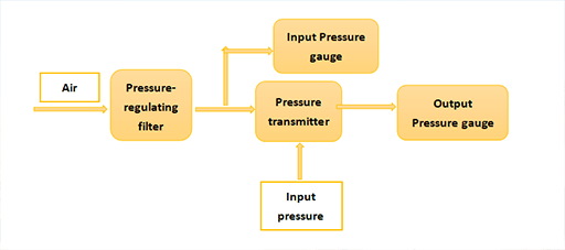
Figure 5: Installing method of pneumatic pressure transmitters.
Pros and Cons of New Type of Pneumatic Pressure Transmitters
This new type of transmitter is an alternative to the QBY pneumatic pressure transmitter. As we know, the QBY transmitter is based on the lever principle. When the signal inputs the measurement chamber, the pressure signal generates a force when acting on the diaphragm (or the bellows or spring tube). This force causes the main lever to rotate around the diaphragm so that the clearance between the nozzle baffles becomes smaller, and the output pressure in the amplifier rises.
This higher pressure enters the feedback bellows to become a feedback force, thus pushing the main lever to rotate in the opposite direction. When the feedback torque is equal to the measured torque, the main lever will be stabilized in balance, and the amplifier output (0.02 MPa~0.1 MPa) is inversely proportional to the measured pressure.
Compared with the new type of transmitter introduced in this article, the QBY transmitter has a wider measurement and adjustment range. The cons are that its structure is more complicated, it is difficult to adjust, lacks stability, and is not resistant to vibration.

Figure 6: A QBY pneumatic pressure transmitter.
The mud pressure in the casing and riser fluctuates greatly, and the mud is corrosive. The new type of pressure transmitter has a special design structure, high precision, good anti-vibration performance, strong corrosion resistance. In addition, it is convenient to install and adjust. There is no continuous gas consumption during the operation.
And it has the advantage of explosion-proof, so it can also be used in harsh environments for pressure detection. The new type of transmitter can transmit the high-pressure value (usually 25 MPa, 40 MPa) to the output signal of the air pressure value of 0~0.2 MPa. But its adjustment range is insufficient, and the system pressure error can only be calibrated. If the transmitter is adjusted excessively, it will inevitably be in an abnormal working state.
Summary
The new type of pneumatic pressure transmitter has been widely used in petroleum machinery factories. After the on-site operation and testing, the transmitter is proved to be stable and reliable. And it can fully meet the requirements of use. Especially in the blowout preventers and choke manifolds applied in petroleum products, the new type one could replace the original pressure transmitter.
Related Info
Use of Differential Pressure Transmitter and Common TroubleshootingDifferent Types of Pressure Transmitters, Working Principle, and How to Select Pressure Transmitter
Transmitter Common Faults & Diagnosis Methods
Piezoelectric Pressure Transducers -- Working Principle, Characteristics and Applications
