


The layout principle of Freon refrigerant pipeline
The main feature of Freon refrigerant is that it dissolves with the lubricating oil. Therefore, it must be ensured that the lubricating oil from each refrigeration compressor can return to the refrigeration compressor after passing through the condenser, evaporator and a series of equipment and pipelines. Come in the crankcase.
(1) Basic principles
1. Ensure that each evaporator is fully supplied with liquid.
2. Avoid excessive pressure loss.
3. Prevent liquid refrigerant from entering the refrigeration compressor.
4. Prevent the lack of lubricating oil in the crankcase of the refrigeration compressor.
5. It should be able to keep airtight, clean and dry.
6. Convenient operation and maintenance should be considered, and proper attention should be paid to neatness.
(2) Principles of piping layout
1, suction tube
1) The suction pipe of the compressor should have a slope of not less than 0.01, sloped towards the compressor. .
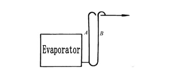
2)When the evaporator is higher than the refrigeration compressor, in order to prevent the liquid refrigerant from flowing into the compressor from the evaporator during shutdown, the evaporator return pipe should be bent upwards to the highest point of the evaporator, and then down to the compressor.

Freon compressor suction pipe
When Freon compressors are operated in parallel, the amount of lubricating oil returning to each refrigeration compressor is not necessarily equal to the amount of lubricating oil taken away from the compressor. Therefore, a pressure equalizing pipe and an oil balance pipe must be installed on the crankcase to make The oil in the crankcase of the refrigeration compressor with more oil return flows into the compressor with less oil return through the oil balance pipe.

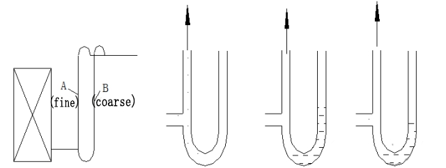
4) The Freon gas in the rising suction standpipe must have a certain flow rate in order to bring the lubricating oil back into the compressor.
5)In a variable load system, in order to ensure that the oil can be returned even under low load, two rising risers can be used, and the two pipes are connected by an oil collecting elbow. The two pipes should be made from the top and the horizontal The tubes are connected.
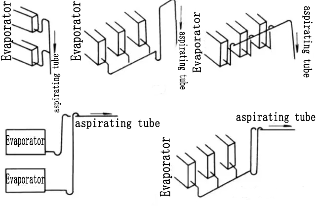
6)When multiple sets of evaporator return air branch pipes are connected to the same suction main pipe, different methods should be adopted according to the relative position of the evaporator and the refrigeration compressor.
2, exhaust pipe
1) In order to prevent lubricating oil or liquid that may condense from flowing back to the compressor, the exhaust pipe of the refrigeration compressor should have a slope of 0.01 to 0.02, and the slope should be towards the oil separator or condenser.
3)When the oil separator is not used, if the compressor is lower than the condenser, the exhaust pipe should be designed as a U-shaped pipe, as shown in the figure, to prevent the condensed liquid refrigerant and lubricating oil from flowing back to the refrigeration compressor

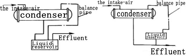
3, the pipeline from the condenser to the liquid reservoir
1) There are two ways to connect the liquid pipe between the condenser and the accumulator;
2)The pipe diameter of the straight-through liquid receiver should be selected according to the liquid flow rate not greater than 0.5m/s during full load operation.
3) It is best to use an angle valve for the inlet valve of the liquid reservoir (the angle valve has a lower resistance).
4) The liquid receiver should be lower than the condenser, and the distance between the center of the angle valve and the condenser liquid outlet should not be less than 200mm.
5) When a straight-through liquid reservoir is used, the supercooled liquid from the condenser will lose its supercooling degree after entering the liquid reservoir.
6) There is a balance pipe on the top of the wave-type accumulator connected with the top of the condenser, and the liquid refrigerant enters and exits from the bottom of the accumulator to adjust and stabilize the refrigerant circulation.
7) The liquid refrigerant from the condenser can directly reach the expansion valve through the liquid pipe.
8) The height difference between the condenser and the wave accumulator should be greater than 300mm. The flow rate of the liquid refrigerant in the pipeline at maximum load and the necessary height difference H value from the condenser liquid outlet to the liquid level of the accumulator are shown in the table.

The liquid velocity and height difference H value in the pipeline
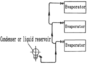
4, the pipeline from the condenser or liquid reservoir to the evaporator
1) In order to avoid flashing gas in the liquid pipe, the liquid supply pipe from the liquid reservoir and the suction pipe of the compressor should be pasted together, and heat insulation materials should be used for heat preservation;
2)When the evaporator is located under the condenser or the liquid reservoir, if the solenoid valve is not installed on the liquid pipe, the liquid pipe should be equipped with an inverted U-shaped liquid seal, and its height should not be less than 2m.

3)When multiple evaporators of different heights are located above the condenser or liquid reservoir, in order to prevent the flash gas that may form from entering the highest evaporator, take over as shown in the figure.
4)The air flow direction of the direct evaporative air cooler should make the hot air contact with the evaporator outlet pipe.

5) Freon cooling pipes supplied by thermal expansion valves generally adopt the form of top in and bottom out to ensure oil return. The tandem platoon should maintain the liquid supply mode of the last group of platoons as top in and bottom out.
6) Cooling piping can be connected in series when the pressure drop is allowed. Freon cooling pipes supplied by thermal expansion valves generally adopt the form of top in and bottom out to ensure oil return. As long as the liquid supply mode of the last group of row pipes is maintained as the top-in and bottom-out, it is not required that each group of rows use the top-in and bottom-out liquid supply mode.
Freon refrigeration system piping commonly used copper pipes or seamless steel pipes, generally use copper pipes when the pipe diameter is less than 20mm, and use seamless steel pipes when the pipe diameter is larger. The piping of the ammonia refrigeration system is made of seamless steel pipes.
In the Freon refrigeration system, the connecting pipes should be minimized to avoid leakage, and the refrigeration pipes are generally welded. Flange connection can be used between the pipeline and the equipment or valve parts, but be careful not to use natural rubber gaskets, nor to apply mineral oil, if necessary, apply glycerin. Copper pipes with a diameter of less than 20mm need to be connected by threaded and flared joints.
The selection of the diameter of the refrigerant pipe should be determined according to its pressure loss equivalent to the change value of the saturated evaporation temperature of the refrigerant, and the corresponding selection chart is available.
The change value of the saturated evaporation temperature of the refrigerant should meet the following requirements:
(1) Freon suction tube, should not be greater than 1 ℃.
(2) Freon exhaust pipe should be 0.5 ℃ -1 ℃.
