


Figure 1: Mechanical sealing.
A mechanical seal is simply a method of containing fluid within a vessel (typically pumps, mixers, etc.) where a rotating shaft passes through a stationary housing or occasionally, where the housing rotates around the shaft.
When sealing a centrifugal pump, the challenge is to allow a rotating shaft to enter the “wet" area of the pump, without allowing large volumes of pressurized fluid to escape.

Figure 2: The challenge is to allow a rotating shaft to enter the “wet" area.
To address this challenge there needs to be a seal between the shaft and the pump housing that can contain the pressure of the process being pumped and withstand the friction caused by the shaft rotating.
2. Why We Need It
Gland packing is still commonly used in many applications, however increasingly users are adopting mechanical seals for the following reasons;
1.The friction of the shaft rotating wears away at the packing over time, which leads to increased leakage until the packing is adjusted or re-packed.
2. The friction of the shaft also means that packing also needs to be flushed with large volumes of water in order to keep it cool.
3. Packing needs to press against the shaft in order to reduce leakage – this means that the pump needs more drive power to turn the shaft, wasting energy.
4. Because packing needs to contact the shaft it will eventually wear a groove into it, which can be costly to repair or replace.
Mechanical seals are designed to overcome these drawbacks.
3. Design
A basic mechanical seal contains three sealing points.
The stationary part of the seal is fitted to the pump housing with a static seal –this may be sealed with an o-ring or gasket clamped between the stationary part and the pump housing.
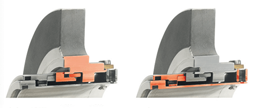
Figure 3: The stationary part (left) and the rotary portion (right).
The rotary portion of the seal is sealed onto the shaft usually with an O ring. This sealing point can also be regarded as static as this part of the seal rotates with the shaft.
The mechanical seal itself is the interface between the static and rotary portions of the seal.
One part of the seal, either to static or rotary portion, is always resiliently mounted and spring loaded to accommodate any small shaft deflections, shaft movement due to bearing tolerances and out-of-perpendicular alignment due to manufacturing tolerances.
3.1 Sealing Points

Figure 4: The primary seal.
The Primary SealWhile two of the sealing points in a seal design are simple static seals, the seal between the rotating and stationary members needs a little more consideration. This primary seal is the basis of all seal design and is essential to its effectiveness.
The primary seal is essentially a spring loaded vertical bearing - consisting of two extremely flat faces, one fixed, one rotating, running against each other. The seal faces are pushed together using a combination of hydraulic force from the sealed fluid and spring force from the seal design. In this way a seal is formed to prevent process leaking between the rotating (shaft) and stationary areas of the pump.
The surfaces of the seal faces are super-lapped to a high degree of flatness; typically 2-3 Helium light-bands (0.00003" / 0.0008mm).
If the seal faces rotated against each other without some form of lubrication they would wear and quickly fail due to face friction and heat generation. For this reason some form of lubrication is required between the rotary and stationary seal face; this is known as the fluid film
3.2 The Fluid Film
In most mechanical seals the faces are kept lubricated by maintaining a thin film of fluid between the seal faces. This film can either come from the process fluid being pumped or from an external source.
The need for a fluid film between the faces presents a design challenge – allowing sufficient lubricant to flow between the seal faces without the seal leaking an unacceptable amount of process fluid, or allowing contaminants in between the faces that could damage the seal itself.
This is achieved by maintaining a precise gap between the faces that is large enough to allow in a small amounts of clean lubricating liquid but small enough to prevent contaminants from entering the gap between the seal faces.

Figure 5: Structure of a pump with mechanical seal.
The gap between the faces on a typical seal is as little as 1 micron - 75 times narrower than a human hair. Because the gap is so tiny, particles that would otherwise damage the seal faces are unable to enter, and the amount of liquid that leaks through this space is so small that it appears as vapor - around 1/2 a teaspoon a day on a typical application.
This micro-gap is maintained using springs and hydraulic force to push the seal faces together, while the pressure of the liquid between the faces (the fluid film) acts to push them apart.
Without the pressure pushing them apart the two seal faces would be in full contact, this is known as dry running and would lead to rapid seal failure.
Without the process pressure (and the force of the springs) pushing the faces together the seal faces would separate too far, and allow fluid to leak out.
Mechanical seal engineering focuses on increasing the longevity of the primary seal faces by ensuring a high quality of lubricating fluid, and by selecting appropriate seal face materials for the process being pumped.
Related Info
Installation and Adjustment of Proportional Valves in Your CarProportional Solenoid Valve - How They Work
Proportional Valve Types for Different Applications
Tips for Troubleshooting Hydraulic Proportional Valves
