


Figure 1: Proportional valves.
1. What It is
A proportional control valve is a valve used to control fluid flow rate by varying the size of the flow passage via a restrictor. The regulated flow rate subsequently adjusts parameters affecting a process in a system, mainly level, pressure and temperature. The other minor parameters include: weight, thickness, humidity, density, Ph, color and viscosity.
1. How They Work
In an automatic control valve, the restrictor is directed by a signal from a controller called an actuator. A proportional control solenoid valve utilizes a solenoid as an actuator for variable valve positioning.

Figure 2: Functional principle of direct-acting solenoid control valves.
2. Operating Principle
In principle it is possible to proportionally control the plunger with variable DC voltage, however in practice static friction on the guide points of the plunger impairs the sensitivity of the valve, which results in greater hysteresis effects (the phenomenon in which the value of a physical property lags behind changes in the effect causing it). To prevent static friction, the normal inlet signal can be converted into a pulse width modulated voltage signal (PWM) using special control electronics.
Pulse-width modulation (PWM) is a technique often used to allow the control of the power supplied to electrical devices. The average value of voltage (and current) fed to the solenoid is controlled by turning the power switch on and off at a fast rate (Figure 2). This kind of control puts the plunger into a very fast but weak amplitude oscillation. The oscillation puts the plunger in a balanced state which maintains its constant sliding friction. The plunger’s oscillation motion has no effect on the fluid’s flow behavior.
The longer the switch is on compared to the off periods, the higher the total power supplied to the solenoid. The term duty cycle describes the proportion of on time, t1, to the cycle duration, T. A low duty cycle corresponds to low power, because the power is off for most of the time. Duty cycle is expressed in percent, 100% being fully on.
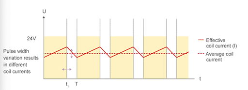
Figure 3: PWM control signal.
In a normally closed solenoid control valve, with zero current fed to the coil, the spring pushes the plunger downwards to a fully closed position, therefore the valve in maintained close. Applying current to the coil generates a magnetic field to move the plunger upward against the return spring. At 100% duty cycle, power is fully fed to the solenoid and the valve is maintained open. Duty cycles between 0 to 100 percent range proportionally change the flow of the valve. For example, a duty cycle of 50% fed to the solenoid moves the spring and the plunger to 50% of the operating range.
3. Selection Criteria
In Continuous flow applications, the choice of appropriate valve size is much more important than with on/off valves. With a high orifice setting the valve can already reach full flow rate at a very small opening (stroke). The remaining stroke is then useless, which impairs resolution and the general control quality of the valve. With an orifice size that is too small on the other hand, the valve won’t reach full flow rate. It is recommended that the pressure drop over the valve should be around 30 % of the total pressure drop within the system.
For correct and accurate control functioning, solenoid control valves must be configured and selected according to their special purpose. The most important parameters for selecting a solenoid control valve are, the kV value (given in m3/h) and the application’s pressure range. The lower the valve’s orifice or the stronger the coil, the higher the pressure the valve can shut-off. The highest kV value needed is calculated based on sizing formulas in Figure 4.

Figure 4: Determination of kV value.
Based on the calculated kV value and the pressure range of the planned application, a correspondingly appropriate valve type and its required orifice can be determined.
Related Info
What is a Proportional Valve?Magnet Pump Troubleshooting: Noisy and Seizing
How to Install a Sump Pump Check Valve: 5 Steps
How To Repair a Pool Spring Flapper Check Valve?
