


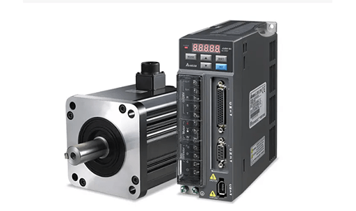
Figure 1: Delta servo motors and drivers.
Servo drive, also known as "servo controller" and "servo amplifier", is a controller used to control servo motors, and its function is similar to that of frequency converters used for ordinary AC motor. Servo drive is part of the servo system and mainly used in high precision positioning systems. The servo driver generally controls the servo motor through three methods of position, speed and torque to achieve high-precision positioning of the transmission system, and it is a high-end product of transmission technology.
1. Parts of Servo Drive
The servo driver contains a DSP (Digital Signal Processor) inside and has its own control algorithm. It forms a servo drive system with the servo motor to complete some functions such as setting, filtering, vibration suppression, compensation, adjustment and monitoring.
The servo driver receives the digital or analog control signal from the upper unit and the feedback signal from the encoder to control the operation of the motor. If the upper unit has a dedicated encoder channel, it can collect the encoder signal from the driver to form a semi-closed loop.
The structure of the servo motor driver mainly includes the control system and the drive system.
1. Control system
It is generally composed of DSP, which collects the current feedback value to close the current loop, collects the encoder signal output speed to close the speed loop, and generates the PWM switching signal of the six switching tubes of the drive system.
2. Drive system
The drive system is mainly composed of the following parts:
a. Rectifier filter circuit, for example, converting 220V AC into about 310V DC and providing it to IPM (Intelligent Power Module).
b. Inside the IPM is a three-phase two-level bridge circuit. The middle part of the upper and lower switch tubes of each phase is connected to the output U, V, W. Through the opening and closing of the 6 switch tubes, it is controlled whether UVW three phases are connected to the ground or the DC high voltage instantaneously.
c. The current sampling circuit may be a Hall current sensor, and the output of the circuit will be connected to the AD port of the control system. Hall elements are magnetic sensors based on the Hall effect, which can detect the magnetic field and its changes, and are generally used in motors to determine the rotor speed.
d. The peripheral circuit of the encoder: its output is connected with the event manager of the DSP.

Figure 2: Panasonic servo drive.
Now, most of the high-performance servo systems use permanent magnet AC servo systems, which include permanent magnet synchronous AC servo motors and full digital AC permanent magnet synchronous servo drives.
The AC permanent magnet synchronous servo driver is mainly composed of a servo control unit, a power drive unit, a communication interface unit, a servo motor and a corresponding feedback detection device. Its structure is shown in Figure 1. The servo control unit includes position controller, speed controller, torque controller and current controller and so on.
AC permanent magnet synchronous drive integrates advanced control technology and control strategy, making it very suitable for high-precision, high-performance drive areas, and also embodies powerful intelligence and flexibility, which is incomparable to the traditional drive system.

Figure 3: AC permanent magnet synchronous servo drive structure.
2. Working Principle of Servo Drive
The servo drive drives the executive motor under the action of the control signal, so whether the driver can work normally or not directly affects the overall performance of the equipment. In the servo control system, the servo drive is equivalent to the brain, and the executive motor is equivalent to the hands and feet.
The mainstream servo drives all use digital signal processors (DSPs) as the control core, which can realize more complex control algorithms, digitization, networking and intelligence. Power devices generally use a drive circuit designed with an IPM as the core. The IPM inside integrates the drive circuit and has fault detection and protection circuits such as overvoltage, overcurrent, overheating, and undervoltage. A soft-start circuit is also added to the main circuit to reduce the impact of the start-up process on the driver.
The power drive unit first rectifies the input three-phase power or mains power through the three-phase full-bridge rectifier circuit to obtain the corresponding DC power. The rectified three-phase electricity or mains electricity drives the three-phase permanent magnet synchronous AC servo motor through the frequency conversion of the three-phase sinusoidal PWM voltage inverter.
The whole process of the power drive unit can be simply said to be the process of AC-DC-AC. The main topology circuit of the rectifier unit (AC-DC) is a three-phase full-bridge uncontrolled rectifier circuit.

Figure 4: Servo drive with emergency stop control.
Servo drives are an important part of modern motion control and are widely used in automation equipment such as industrial robots and CNC machining centers. In particular, the servo drive used to control the AC permanent magnet synchronous motor has become a hot research topic at home and abroad.
3. Servo Drive Control Mode
Generally, servo drives have three control modes: position control mode, torque control mode and speed control mode.
3.1 Position Control Mode
In the position control mode, the rotation speed is generally determined by the frequency of externally input pulses, and the rotation angle is determined by the number of pulses. Some servos can directly assign values to speed and displacement through the communication method. Since the position mode can have very strict control on the speed and position, it is generally used in positioning devices.
3.2 Torque Control Mode
The torque control method is to set the magnitude of the external output torque of the motor shaft through the input of the external analog quantity or the address assignment directly. The set torque can be changed by changing the setting of the analog quantity immediately, or this is achieved by changing the value of the corresponding address through communication method.
This control method is mainly used in winding and unwinding devices that have strict requirements on the force of the material, such as wire winding devices or optical fiber pulling equipment. The torque setting should be changed at any time according to the change of the winding radius to ensure that the force of the material does not change with the change of the winding radius.
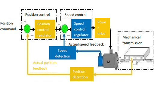
Figure 5: Control methods of the servo drive.
3.3 Speed Control Mode
In this mode, the rotational speed can be controlled by analog input or pulse frequency.
1. Pulse frequency
It is to control the rotation speed of the servo motor through the pulse frequency sent to the servo drive by the upper controller (such as PLC). This method is the same as the position mode.
2. Analog input
This method is similar to the torque mode, and 0-10V corresponds to different speeds. When the external input analog quantity is set to different voltages, the servo motor will output the corresponding speed.
In the speed mode, the servo system itself cannot do positioning. To achieve the positioning function, the position signal of the motor or the position signal of the load should be fed back to the upper computer, and then the upper computer will perform arithmetic control. To put it bluntly, it is necessary to additionally detect the position of the motor or load.
The position mode also supports the outer loop of the load to directly detect the position signal. At this time, the encoder at the motor shaft end only detects the motor speed, and the position signal is provided by the detection device at the final load end. The advantage of this is that it can reduce the error in the intermediate drive process and increase the positioning accuracy of the whole system.
4. Function of Servo Drive
Servo drive is a controller that drives a servo motor to make the device generate power and operate normally. There are many functions of servo drive, including:
1. Parameter grouping setting, arbitrary switching of control mode online.
2. Controlling power AC input, settable wide voltage input.
3. Instantaneous power failure and rapid shutdown protection function.
4. Regenerative braking, dynamic braking function.
5. Absolute value system voltage monitoring, low voltage warning function.
6. Debugging software supporting parameter management, monitoring, oscilloscope function.
As a professional distributor, Okmarts can provide various servo drivers of different brands, such as ac servo motor controller. If you are interested, please contact us!
Related Info
Three Control Methods of Servo MotorServo Motors: Construction, Types, Advantages & Applications
AC Servo Motor Construction and Working
Positive Displacement Pump vs Centrifugal Pump
Servo Motor: Basics, Work Principle & Selection
