


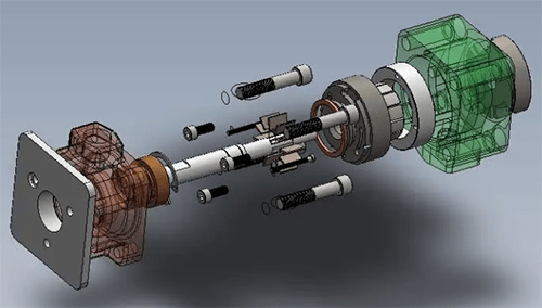
Figure 1: Hydraulic vane pump diagram.
With the development of hydraulic technology, vane pump, as an indispensable power element, has been more and more deeply penetrated into various fields such as hydraulic systems, and has played a pivotal role. The following will introduce the classification, working principle, application and precautions of hydraulic vane pumps in detail.
1. Types of Hydraulic Vane Pumps
Vane pumps can be divided into single-acting vane pumps, double-acting vane pumps and multi-acting vane pumps according to the times of oil suction and discharge in the vane chamber during each revolution of the pump shaft.
According to whether the displacement is variable, it is divided into fixed displacement pump and variable displacement pump.
According to the different parts of the vanes setting, it is divided into a general vane pump (the vanes are on the rotor) and the cam rotor vane pump (the vanes are on the stator).
According to different pressure levels, it is divided into medium and low pressure vane pumps (below 7MPa), medium and high pressure vane pumps (below 16MPa) and high pressure vane pumps (below 20-30MPa).
In addition, the hydraulic vane pump can be divided into: single stage pump, double pump, double stage pump and compound pump according to the structure.
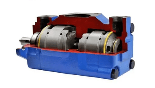
Figure 2: Double vane hydraulic pump.
The single-acting vane pump is generally suitable to be made into a variable displacement pump because the flow can be adjusted by changing the eccentric distance between the stator and the rotor. However, there are many relatively moving parts, and it has the disadvantages of large leakage, inconvenient adjustment, and is not suitable for high pressure.
Double-acting vane pumps can only be made into fixed displacement pumps. These pumps have high pressure, uniform oil delivery, and are widely used. Quantitative vane pumps can be made into single-stage, double-stage (the oil circuits of the two pumps are connected in series, and the pressure is twice that of the single-stage pump), duplex (the oil circuits of the two pumps are connected in parallel, and are driven by a common shaft, which can obtain a variety of flow), and compound vane pump.
2. How Does a Hydraulic Vane Pump Work
When the vane pump rotor rotates, under the action of centrifugal force and pressure oil, the tip of the vane is close to the inner surface of the stator. In this way, the working volume formed by the two vanes and the inner surface of the rotor and the stator first change from small to large to sucks oil, and then change from large to small to discharge oil. When the vanes rotate once, the pump completes oil suction and oil discharge once.
2.1 Working Principle of Single Acting Vane Pump
The pump is composed of rotor 2, stator 3, vane 4 and end cover, etc. The inner surface of the stator is a cylindrical bore. There is an eccentricity between the rotor and the stator. The vane can slide flexibly in the slot of the rotor. Under the action of the centrifugal force when the rotor rotates and the pressure oil enters the root of the vane, the top of the vane is close to the inner surface of the stator.
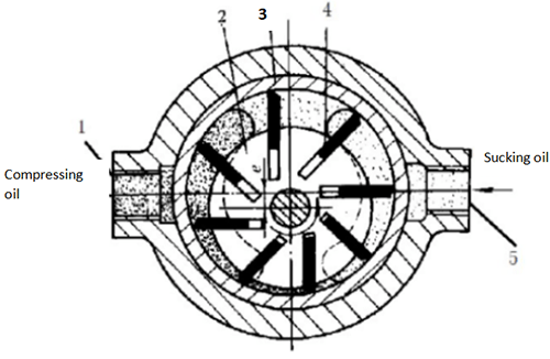
Figure 3: Working principle diagram of single acting vane pump.
1-Oil discharge port 2-Rotor 3-Stator 4-vane 5-Oil suction port
When the rotor rotates in the counterclockwise direction, the vanes on the right side in the figure extend outward, the volume of the sealed working chamber gradually increases, and a vacuum is generated, so the oil is sucked in through the oil suction port 5. On the left side of the figure, the vanes are retracted inward, the volume of the sealing chamber is gradually reduced, and the oil in the sealing chamber is pushed out through oil discharge port 1 to the system.
Structural features of the single-acting pump:
1.This kind of pump sucks and discharges oil once during one rotation of the rotor, so it is called a single-acting pump.
2.The rotor is subjected to radial hydraulic unbalanced force, so it is also called an unbalanced vane pump, and its bearing load is large.
3.By changing the eccentricity between the stator and the rotor, the displacement of the pump can be changed, so this kind of pump can be a variable displacement pump.
2.2 Working Principle of Double Acting Vane Pump
Its working principle is similar to that of a single-acting vane pump, the difference is that the stator and rotor are concentric.
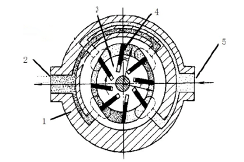
Figure 4: Working principle diagram of double-acting vane pump.
1-Stator 2-Oil discharge port 3-Rotor 4-Vane 5-Oil suction port
When the rotor rotates clockwise as shown in the figure, the volume of the sealed working chamber gradually increases at the upper left corner and the lower right corner, which is the oil suction area. And the volume gradually decreases at the lower left corner and the upper right corner, which is the oil discharge area. There is a section of oil sealing area between the oil suction area and the oil discharge area to separate them.
The instantaneous flow of the double-acting vane pump is pulsating, and the pulsation rate is small when the number of vanes is a multiple of 4. For this reason, the number of vanes of the double-acting vane pump is generally 12 or 16.
Structural features of double-acting pump:
1.The stator and rotor are concentric.
2.Each time the rotor of this pump rotates, each sealed working chamber completes the oil suction and oil compression actions twice, so it is called a double-acting vane pump.
3.The two oil suction areas and the two oil discharge areas of the pump are radially symmetrical, and the hydraulic pressure acting on the rotor is radially balanced, so it is also called a balanced vane pump.
2.3 Variable Displacement Vane Pump
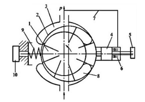
Figure 5: Working principle diagram of the pressure-limiting variable vane pump.
1—Rotor; 2—Stator; 3—Oil discharge port; 4—Piston; 5—Screw; 6—Feedback cylinder; 7—Pipeline; 8—Oil suction port; 9—Pressure adjusting spring; 10—Pressure adjusting screw
The pressure-limiting variable displacement vane pump is a single-acting vane pump. Its working principle is shown in the figure. The rotation center of the rotor is fixed, and the eccentric installation of the stator sleeve relative to the rotor is movable and adjustable.
A feedback oil cylinder 6 and a piston 4 are set on the right side of the stator sleeve, and the left side is set with a pressure regulating spring 9 and a pressure regulating screw 10. The action oil of the feedback cylinder comes from the oil discharge port of the pump, so when the pump is working normally, the stator is in a relatively balanced position under the interaction of the feedback pressure of the discharged oil and the pressure regulating spring 9.
Structural features of variable vane pump:
1.Each time the rotor of the pump rotates, each sealed volume completes oil suction and oil compression once.
2.By changing the eccentricity between the stator and the rotor, the displacement of the pump can be changed, so it is called a variable vane pump.
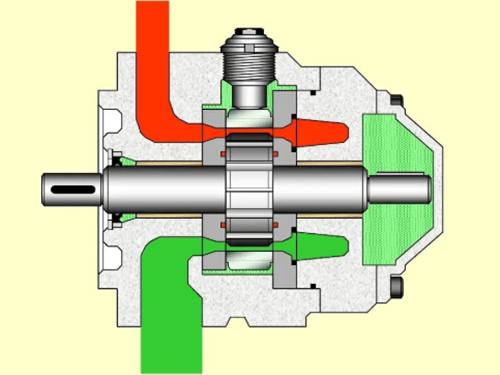
Figure 6: Variable vane pump.
3. Applications of Hydraulic Vane Pump
The double-acting vane pump not only has balanced radial force on the rotor, stable operation, uniform oil delivery and low noise, but also has larger flow rate, compact structure and small volume. The disadvantage of the double-acting vane pump is complicated structure, poor oil suction characteristics, and it is more sensitive to oil pollution. They are widely used in various medium and low pressure hydraulic systems to complete medium-load work.
Compared with the double-acting vane pump, the single-acting vane pump has a complex structure, large size, and is affected by radial unbalanced force, resulting in high noise, low volumetric efficiency and mechanical efficiency, and serious flow pulsation. However, it is easy to realize flow adjustment, and is often used in hydraulic systems with fast and slow motion, which can reduce power loss, reduce oil heating, simplify oil circuits, and save hydraulic components.
Vane pumps are generally used in hydraulic systems with medium and high speed and medium force. Medium and small flow vane pumps are often used in throttling hydraulic systems; large flow vane pumps are only used in non-regulated hydraulic systems in order to avoid excessive losses.
Hydraulic vane pumps are widely used in the following areas:
Plastic processing machinery, pressure machinery, machine tools, etc., for general industrial use;
Construction machinery, agricultural machinery, automobiles, etc. in mobile machinery;
Metallurgical machinery, lifting devices, roll adjustment devices, etc. for the iron and steel industry;
Flood control gates and dam devices, river bed lifting devices, bridge control mechanisms, etc. for civil and hydraulic engineering;
Deck lifting machinery (winches), bulkhead valves, stern thrusters, etc. for ships.
4. What Should be Paid Attention to When Using a Vane Pump?
The vane pump is a pump in which the vanes in the rotor slots are in contact with the pump casing (stator ring), and the inhaled liquid is pressed from the oil inlet side to the oil discharge side. The following problems should be paid attention to when using a hydraulic vane pump.
1. When the rotational direction of the pump changes, the oil suction and discharge direction also changes. The vane pump has a prescribed rotation direction and does not allow reversal rotation. Because the rotor vane slots are inclined, and the vanes have a chamfered angle. The throttle groove and suction and discharge ports on the oil distribution plate are designed according to the established rotational direction. Reversible vane pumps must be specially designed.
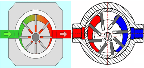
Figure 7: Radially mounted vanes and vanes not mounted radially.
2. If the clearance of the vane in the vane slot is too large, the leakage will increase, and if the clearance is too small, the vane cannot extend and retract freely, which will lead to abnormal operation.
3. The axial clearance of the vane pump has a great influence on volume efficiency ηv.
1) Small vane pump --0.015~0.03mm
2) Medium vane pump --0.02~0.045mm
4. The temperature of the oil should generally not exceed 55°C, and the viscosity should be between 17 and 37mm2/s. If the viscosity is too large, it will be difficult to suck oil; if the viscosity is too small, the leakage will be serious.
Related Info
Structural Characteristics of Gear Pump and Its Working PrincipleHow to Choose a Gear Pump?
Piston Pump: Working Principle, Types, and Features
What are Hydraulic Piston Pumps?
What is the Difference Between Piston and Plunger Pumps
