


Figure 1: Various types of gear reducers.
Gear ratio, i.e., the reduction ratio of the reducer, refers to the ratio of the instantaneous input speed to the output speed in the reduction mechanism, and is represented by the symbol "i".
How to Calculate Gear Ratio?
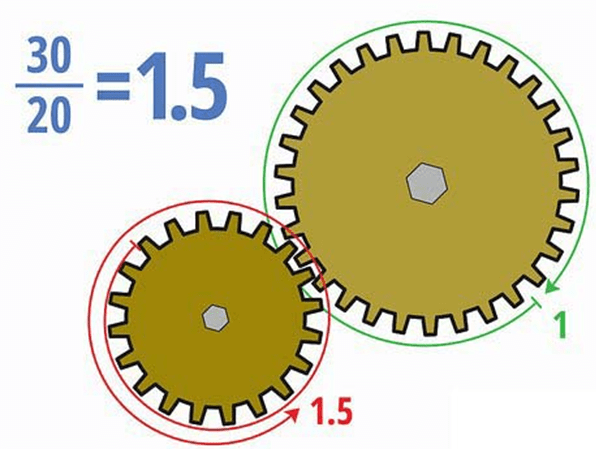
Figure 2: Calculating gear ratio by teeth numbers.
Gear ratio calculation formular: gear ratio =input (rotational) speed ÷ output (rotational) speed.
Gear train ratio calculation method: gear ratio = the number of driven gear teeth ÷ the number of driver gear teeth. In case of a multi-stage gear reduction, divide the number of driven gear teeth of all meshing pairs of gear sets with the number of teeth of the driving gear, and then multiply the obtained results.
Calculation formular of reduction ratio of belt, chain and friction wheel: reduction ratio = driven wheel diameter ÷ driver wheel diameter
The general method of expressing the gear ratio is to use 1 as the denominator, and use ":" to connect the ratio between the input speed and the output speed. If the input speed is 1500r/min and the output speed is 25r/min, then the gear ratio is: i=60:1.
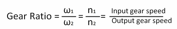
Figure 3: Calculating gear ratio by angular velocity, gear speed in revolutions per minute (RPM), gear diameter and teeth number.
Generally speaking, the marked reduction ratio of the reduction mechanism is the actual reduction ratio. But when it comes to some special reducers such as cycloid reducer or harmonic reducer, the ratio is sometimes rounded to the nearest whole number without denominator. For example, the actual reduction ratio may be 28.13, but it is generally marked with 28.
Tips for Model Selection of a Gear Reducer
First you need to determine the type of reducer and then the input power and required output torque. Calculate the reduction ratio of the reducer based on the rotational speed of the input shaft and the required rotational speed of the output shaft. According to the actual usage such as: daily operating time, impact load, switching frequency, etc., determine the operating condition factor. Try to choose a reduction ratio close to the ideal one: reduction ratio = servo motor speed ÷ reducer output shaft speed.
| Gearing | Worm Gear | |||||||
| Maximum Input Speed | 1,800 rpm | |||||||
| Gear Ratio | 3.5:1 | 10:1 | 15:1 | 20:1 | 30:1 | 40:1 | 48:1 | 60:1 |
| Rated Input Hp at 1800 rpm |
0.84 | 0.33 | 0.27 | 0.22 | 0.15 | 0.10 | 0.09 | 0.075 |
| Rated Output Torque lbs-inch |
102 | 102 | 102 | 105 | 120 | 112 | 96 | 75 |
Figure 4: Diagram of Torque Transmission SW-1 Worm Gear Speed Reducer Performance Specifications - All Models.
Determine the specifications of the reducer according to the model, load torque, gear ratio, and output speed. The following questions are often considered.
1. What equipment is the reducer used on, so as to determine the safety factor SF (SF = the rated power of the reducer divided by the motor power), the installation form (orthogonal shaft, parallel shaft, output hollow shaft key, output hollow shaft disc padlock, etc.), etc.
2. Reducer power, pole count (4P, 6P or 8P)
3. The ambient temperature around the reducer (determining the check of the thermal power of the reducer)
4. The check of the radial force and axial force of the output shaft of the reducer, axial force and radial force required
Related Info
How to Maintain a Pressure Transmitter?What is a Smart Pressure Transmitter?
Characteristics of Smart Pressure Transmitters
What is a Gear Reducer?
10 Things to Consider when Choosing a Pressure Transmitter
