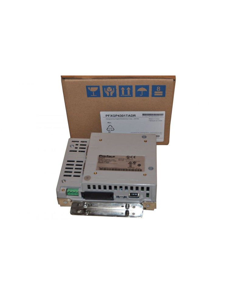
Pro-face GP-4301T 5.7-INCH Rating:24VDC
Standard product information
Family
HMI
Series
GP4000R Series
Size
5"
Model
PFXGP4301TADR
Global Code
PFXGP4301TADR
Product Features
Rear Mount 5" DC Analog
Repair Status
✔ (Maintenance service is available, able to be maintained.)
Display specifications
Display type
TFT Color LCD
Display size
5.7"
Resolution
320 x 240 pixels (QVGA)
Effective display area
W115.2 x H86.4 mm [W4.54 x H3.40 in.]
Display colors
65,536 colors (No blink) / 16,384 colors (Blink)
Backlight
White LED (Not user replaceable. When replacement is required, contact your local distributor.)
Backlight service life
50,000 hrs. or more (each in continuous operation at 25 °C [77 °F] before backlight brightness decreases to 50%)
Brightness control
16 Levels (Adjusted with touch panel or software)
Touch panel type
Resistive Film (analog)
Touch panel resolution
1,024 x 1,024
Touch panel lifetime
1,000,000 times or more
Language fonts
Japanese: 6,962 (JIS Standards 1 & 2) (including 607 non-kanji characters), ANK: 158 (Korean, Traditional Chinese, Simplified Chinese, Thai and Cyrillic can be added from the font setting of the screen editor. )
Character sizes
Standard font: 8 x 8, 8 x 16, 16 x 16 and 32 x 32 pixel fonts, Stroke font: 6 to 127 pixel fonts, Image font: 8 to 72 pixel fonts
Font sizes
Standard font: Width can be expanded up to 8 times. Height can be expanded up to 8 times.*1
8 x 8 dots
40 char. x 30 rows
8 x 16 dots
40 char. x 15 rows
16 x 16 dots
20 char. x 15 rows
32 x 32 dots
10 char. x 7 rows
1.Other font sizes can be set up with the Editor software.
Electrical specifications
Rated input voltage
24 Vdc
Input voltage limits
19.2 to 28.8 Vdc
Allowable voltage drop
5 ms or less
Power consumption
10.5 W or less
In-rush current
30 A or less
Noise immunity
Noise Voltage : 1,000 Vp-p
Pulse Duration : 1 µs
Rise Time : 1 ns
(via noise simulator)
Voltage endurance
1,000 Vac, 20 mA for 1 minute (between power terminal and FG terminals)
Insulation resistance
500 Vdc, 10 MΩ or more (between power terminal and FG terminals)
Environmental specifications
International safety standards
Surrounding air temperature
0 to 55 °C [32 to 131 °F]
Storage temperature
-20 to +60 °C [-4 to 140 °F]
Ambient humidity
10 to 90 % RH (Wet bulb temperature: 39 °C [102.2 °F] max. - no condensation)
Storage humidity
10 to 90 % RH (Wet bulb temperature: 39 °C [102.2 °F] max. - no condensation)
Dust
0.1 mg/m3 (10-7 oz/ft3) or less (non-conductive levels)
Pollution degree
For use in Pollution Degree 2 environment
Corrosive gases
Free of corrosive gases
Air pressure (altitude range)
800 to 1,114 hPa (2,000 m [6,561 ft.] above sea level or less)
Vibration resistance
IEC/EN 61131-2 compliant
5 to 9 Hz single amplitude 3.5 mm [0.14 in.]
9 to 150 Hz fixed acceleration: 9.8 m/s2
X, Y, Z directions for 10 cycles (approx. 100 min.)
Concussion resistance
IEC/EN 61131-2 compliant 147 m/s2, X, Y, Z directions for 3 times
Electrostatic discharge immunity
Contact Discharge Method: 6 kV (IEC/EN61000-4-2 Level 3)
Memory
Application memory
When using GP-Pro EX:
- Media: FLASH EPROM
- Screen Area: 16MB *Use the screen area when the user font area's capacity is exceeded - for example, when an image font or a picture font is used.
- User Font Area: 8MB
- Logic Program Area: 132KB (Equivalent to 15,000 steps) *Up to 60,000 steps can be converted in software. However, this reduces application memory capacity (for screen data) by 1 MB.
- Free Space: None
Removable System: No
Backup memory
When using GP-Pro EX:
- Screen Area: SRAM 320KB
- Variable Area: SRAM 64KB
Battery: Replaceable battery / Primary battery for clock data backup
Clock accuracy
±65 sec./month (deviation at room temperature and power is OFF)*2
2.Depending on the operating temperature and age of unit, the clock can deviate from -380 to +90 sec./month. For systems where this level of deviation is a problem, the user should monitor and make adjustments when required.
Interface specifications
Serial (COM1)
Asynchronous Transmission: RS-232C, Data Length: 7 or 8 bits, Stop Bit: 1 or 2 bits, Parity: None, Even or Odd, Data Transmission Speed: 2,400 to 115,200 bps, Connector: D-Sub 9 (plug)
Serial (COM2)
Asynchronous Transmission: RS-422 / 485, Data Length: 7 or 8 bits, Stop Bit: 1 or 2 bits, Parity: None, Even or Odd, Data Transmission Speed: 2,400 to 115,200 bps, 187,500 bps (MPI), Connector: D-Sub 9 pin (plug)
USB (Type A)
Conforms to USB 2.0 (Type A) x 1
Power supply voltage: 5 Vdc ±5 %
Output Current: 500 mA or less
Communication distance: 5 m [16.4 ft.] or less
USB (mini-B)
Conforms to USB 2.0 (mini-B) x 1, Communication Distance: 5 m [16.4 ft] or less
Ethernet
IEEE802.3i / IEEE802.3u, 10BASE-T / 100BASE-TX, Connector: Modular jack (RJ-45) x 1
SD card
SD Card Slot x 1
Structural specifications
Grounding
Functional grounding: Grounding resistance of 100 Ω, 2mm2 (AWG 14) or thicker wire, or your country's applicable standard. (Same for FG and SG terminals)
Cooling method
Natural air circulation
Structure
IP20*3
External dimensions
W155.6 x H123.4 x D59.7 mm [W6.13 x H4.86 x D2.35 in.]
Panel cut-out dimensions
Standard Mount: W118.8 x H90 mm [W4.68 x H3.54 in.]
Flat Mount: W143 x H109 mm [W5.63 x H4.29 in.]*4
Weight
1 kg [2.21 lb] or less
3.Protection structure equivalent to IP67F can be expected if you affix the Overlay (sold separately) on the screen of the unit and the surroundings. Pro-face does not guarantee the protective structure. Consider the the protective structure in combination with a panel or a resin plate within your quality assurance range. For details, please refer to GP4000 Series Hardware Manual.
4.As for dimensional tolerance everything +0.5/-0 mm [+0.02/-0 in.] and R in angle are below R1 [R0.04in.]
Dimensions
External dimensions
Installation with Installation Fasteners attached to the top and bottom surfaces of the GP unit
Installation with Installation Fasteners attached to the sides of the GP unit
Installation with Installation Fasteners attached to the top and bottom surfaces of the GP unit
Installation with Installation Fasteners attached to the sides of the GP unit
Installation with Installation Fasteners attached to the top and bottom surfaces of the GP unit
Installation with Installation Fasteners attached to the sides of the GP unit
Panel cut-out dimensions
a) |
|
Installation positions of stud bolts or positions of boss molds when attaching installation brackets at the top and bottom surfaces of the GP unit |
b) |
|
Installation positions of stud bolts or positions of boss molds when attaching installation brackets on either side of the GP unit |
d) |
|
4-M4 x 10L stud bolts (no foreign material present on the base due to sparking or similar phenomena) or boss molds |
e) |
|
Center of the display area |
A |
B |
C |
R |
|
Panel Type *1 |
Resin Boss Type *2 |
|||
118.8mm (+0.5, -0mm) (4.68in. [+0.02, -0in.]) |
90mm (+0.5, -0mm) (3.54in. [+0.02, -0in.]) |
1.6mm (0.06in.) to 3.2mm (0.13in.) (SPCC "JIS G3141" or SECC "JIS G3313") |
2mm (0.08in.) or more |
1mm (0.04in.) maximum |
Note: If you are designing the panel with a material other than sheet metal, ensure that the material has sufficient strength.
*1 Panel type: Weld the stud bolts to the panel, and then tighten the nuts to fasten the GP unit to the panel.
*2 Resin boss type: Tighten the screws to attach the GP unit to the bosses of the resin boss-molded product.
Attaching Installation Brackets |
||
X1 |
Y1 |
X2 |
Y2 |
43 (±0.15) |
69.5 (±0.15) |
85.6 (±0.15) |
43 (±0.15) |
Note: Note that the panel cut dimensions have been calculated with the display area, not the panel cut (A or B), as the reference.
a) |
|
Installation positions of stud bolts or positions of boss molds when attaching installation brackets at the top and bottom surfaces of the GP unit |
b) |
|
Installation positions of stud bolts or positions of boss molds when attaching installation brackets on either side of the GP unit |
d) |
|
4-M4 x 10L stud bolts (no foreign material present on the base due to sparking or similar phenomena) or boss molds |
e) |
|
Center of the display area |
A |
B |
C |
R |
||
A1 |
A2 |
Panel Type *1 |
Resin Boss Type *2 |
||
143mm (+0.5, -0mm) |
109mm (+0.5, |
1.6 mm (0.06in.) (SPCC "JIS G3141" or SECC "JIS G3313") |
2 mm (0.08in.) maximum |
1 mm (0.04in.) maximum |
|
70.5mm (+0.25, |
72.5mm (+0.25, |
Note: If you are designing the panel with a material other than sheet metal, ensure that the material has sufficient strength.
*1 Panel type: Weld the stud bolts to the panel, and then tighten the nuts to fasten the GP unit to the panel.
*2 Resin boss type: Tighten the screws to attach the GP unit to the bosses of the resin boss-molded product.
Attaching Installation Brackets |
||
X1 |
Y1 |
X2 |
Y2 |
43 (±0.15) |
69.5 (±0.15) |
85.6 (±0.15) |
43 (±0.15) |
Note: Note that the panel cut dimensions have been calculated with the display area, not the panel cut (A or B), as the reference.
External dimensions with cable
NOTE: All the above values are designed with cable bending in mind. The dimensions given here are representative values depending on the type of connection cable in use. Therefore, these values are intended for reference only.
You can enjoy free shipping when your total purchase value is greater than or equal to $300 (a few items excluded).
We promise if you find there are quality problems with the goods received, we can provide you with return and exchange services.
Our telephone customer service staff work online form 9 am to 5 pm working days (Monday to Friday,Beijing Time).
We promise that all the products you buy on your platform are genuine.