


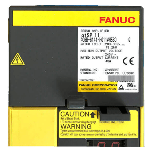
Figure 1: Fanuc Spindle Amplifier Drive Module.
FANUC CNC system has two mainstream servo drive amplifiers - αi and βi series servo drive amplifiers.
The αi series servo drive amplifier is a high-performance, cost-effective drive product with modular structure, which consists of three servo modules, including: power amplifier (PSM: Power Supply Module), Spindle Amplifier (SPM: Spindle Module), servo amplifier (SVM: Servo Module).
PSM servo amplifier: It mainly provides power and safety control for servo module and spindle module.
SPM servo amplifier: mainly provides power and control for the spindle motor.
SVM servo amplifier: mainly provides power and control for servo motors, such as servo drive amplifiers for X, Y, and Z axes.
Spindle Alarm Codes and Solutions
The followings are some common FANUC spindle alarms and troubleshooting methods. Hope information below will help you.
1. SP9001 Motor Overheating (Amplifier Alarm Code: 01)
Cause for alarm: The software detects that the spindle motor is overheated.
Troubleshooting:
1) Check the temperature of the spindle motor. If the temperature is normal, check the temperature sensor.
2) Check whether the cooling fan is normal.
3) Check whether the spindle is under high load (over rated value) for a long time.
4) When this alarm occurs, the third-party electro-spindle should check the type of thermal resistance, and then check parameters P4397#4 and P4134.
2. SP9002 Excessive Speed Deviation
Cause for alarm: The feedback speed of the spindle cannot keep up with the commanded speed of the spindle. (The actual speed of the motor is quite different from the command speed)
Troubleshooting:
1) Check whether the load is too heavy and the spindle cannot keep up with the commanded speed.
2) Check whether the initialization parameters of the spindle motor are abnormal.
3) Check amplifier and spindle motor for any abnormality.
4) Change parameter P4082.
3. SP9003 Fuse Blown
Cause for alarm: The DC bus fuse in the spindle amplifier is blown.
Troubleshooting:
Check for hardware damage.
1) Check the peripheral wiring circuit, especially the circuit related to the power cord.
2) Replace the spindle motor amplifier.
3) Check the insulation state of the motor.
4. SP9004 Power Supply Phase Loss
Cause for alarm: Phase loss detected on power supply. If there is lacking one phrase of the three-phase AC 200V of the main shaft, the control board can detect it and issue an alarm No. 04.
Troubleshooting:
1) Check the input interface of the power cord.
2) Check the wiring of the CX48 interface.
3) Note the winding switching between the high winding motor and the low winding motor.
5. SP9006 Thermal Relay Disconnected
Cause for alarm: The motor temperature sensor is disconnected.
Troubleshooting:
1) Reinitialize the spindle motor parameters, and pay attention to the encoder parameters.
2) Check the feedback circuit of the spindle motor.
3) Check the temperature sensor of the spindle motor.
4) Check the spindle motor amplifier.
6. SP9007 Overspeed
Cause for alarm: The motor exceeds 115% of the maximum speed (parameter standard setting).
Troubleshooting:
1) Check the initialization parameters of the spindle motor.
2) Check the phase sequence of the spindle power cable.
3) Check the spindle motor amplifier.
7. SP9009 Main Circuit Overheating
Cause for alarm: The temperature of the radiator used to cool the power semiconductor rises abnormally.
Troubleshooting:
1) Improve the cooling capacity of the cooling device.
2) Check the external radiator cooling fan.
3) Replace the spindle amplifier.
8. SP9010 Low Input Power Supply Voltage
Cause for alarm: The input power supply voltage of the spindle amplifier is low.
Troubleshooting:
1) Check amplifier input supply voltage.
2) Replace the power input cable or replace the amplifier.
9. SP9011 DC Link Overvoltage
Cause for alarm:
When the spindle motor rotates at high speed, the inertia is large. So when the power supply of the motor is cut off, the regenerative braking function of the spindle does not work, and the spindle motor cannot stop immediately.
Troubleshooting:
1) Use the common power supply to detect the overvoltage of the DC Link part (the common power supply alarm displays 7), check the input voltage, and if possible, use the filter to check. It may cause voltage stability degradation.
2) If the selection of the public power supply is wrong, exceeding the maximum output specification of the public power supply, please contact the FANUC representative to re-calculate whether the selection of the power supply module is correct.
3) Confirm that the spindle initialization parameters are normal, and try to modify the parameter P4672 at the same time.
4) Replace the amplifier.
10. SP9012 (FANUC Spindle Amplifier Alarm 12) DC Link Circuit Overcurrent
Cause for alarm: Spindle motor overcurrent.
Troubleshooting:
1) Check the initialization of the parameters specific to the spindle motor.
2) Check the insulation filling of the cable and check whether the phase sequence of the power cable is connected correctly.
3) Replace the spindle amplifier.
4) If this alarm occurs when switching windings, there may be a problem with the contactor and PMC timing.
11. SP9013 CNC Data Memory Failure
Cause for alarm: The spindle amplifier control circuit is abnormal.
Troubleshooting:
Confirm hardware damage and replace spindle amplifier side plate.
12. SP9014 Serial Spindle Warning
Cause for alarm: An amplifier not registered in the spindle software is used.
Troubleshooting:
The spindle data is accidentally erased, and the spindle software needs to be updated.
13. SP9015 Spindle Switching Failure
Cause for alarm: The sequence of spindle switching/output switching is abnormal. (The switching operation sequence of output switching control or spindle switching control is incorrect.)
Troubleshooting:
1) When the spindle output is switched, an alarm will be generated, and the PMC signal needs to be changed to switch the spindle.
2) If an alarm occurs when the spindle rotates normally, parameter P4160 should be increased.
14. SP9016 Memory Failure
Cause for alarm: RAM used for external data of spindle amplifier is abnormal.
Troubleshooting:
If the hardware is damaged, replace the spindle amplifier.
15. SP9017 Serial Spindle Alarm
Cause for alarm: Abnormal spindle amplifier ID is detected.
Troubleshooting:
Replace the spindle amplifier.
16. SP9018 Program ROM Checksum Error
Cause for alarm: The ROM device of the spindle amplifier data is abnormal.
Troubleshooting:
Replace the spindle amplifier.
17. SP9019 Excessive U Phase Current Offset
Cause for alarm: Abnormality was detected in the spindle amplifier part (the initial value of the U-phase current detection circuit was abnormal).
Troubleshooting:
Replace the spindle amplifier.
18. SP9020 Excessive V Phase Current Offset
Cause for alarm: An error is detected in the spindle amplifier unit (the initial value of the V-phase current detection circuit was abnormal).
Troubleshooting:
Replace the spindle amplifier.
19. SP9021 Position Sensor Polarity Error
Cause for alarm: The polarity of the position sensor is wrong.
Troubleshooting:
Set P4000#0 and P4001#4 correctly.
20. SP9022 Serial Port Spindle Warning
Cause for alarm: The overload current of the spindle amplifier is detected.
Troubleshooting:
1) Make sure that the spindle initialization parameters are set correctly.
2) Change the operating conditions of the spindle motor to reduce the load.
3) Check whether the parameters of the 2-winding motor and the winding switching part in the ladder diagram are correct.
4) Replace the spindle amplifier.
|
Alarm code |
Cause |
|
A |
Program ROM exception (not installed) |
|
AL-01 |
Motor overheating |
|
AL-02 |
Excessive speed deviation |
|
AL-03 |
DC Link fuse blown |
|
AL-04 |
Phase loss detected in 3-phase input of PSM main circuit |
|
AL-05 |
Control power fuse blown |
|
AL-06 |
Overspeed temperature sensor abnormal or temperature sensor cable disconnected |
|
AL-07 |
Motor speed too high |
|
AL-08 |
High input voltage |
|
AL-09 |
High load on main circuit part or abnormal increase in heat sink temperature of main circuit of spindle amplifier module |
|
AL-10
|
Low input voltage. The 432 alarm is very likely that when the peripheral DC24V is suddenly connected to the I/O point, the voltage is dropping down, and suddenly changes low but no short circuit, and then the voltage rises again. |
|
AL-11 |
The voltage of DC Link of the main circuit is too large. |
|
AL-12 |
The current of DC Link of the main circuit is too large. |
|
AL-13 |
CPU internal data memory abnormal |
|
AL-14 |
ROM alarm |
|
AL-15 |
Spindle switch/output switch alarm |
|
AL-16 |
RAM exception |
|
AL-18 |
Program ROM checksum error |
|
AL-19 |
Excessive offset voltage of U-phase current detection circuit |
|
AL-20 |
Excessive offset voltage of V-phase current detection circuit |
|
AL-21 |
Position sensor polarity error |
|
AL-22 |
TSA offset alarm |
|
AL-23 |
ER offset alarm |
|
AL-24 |
Serial transmission data error |
|
AL-25 |
Serial transmission data stop |
|
AL-26 |
Error in speed detection signal for Cs contour control |
|
AL-27 |
Position encoder signal abnormal |
|
AL-28 |
Abnormal position detection signal for Cs contour control |
|
AL-29 |
Short-term overload |
|
AL-30 |
Input circuit overcurrent |
|
AL-31 |
The motor does not rotate at the commanded speed, but stops, or rotates at a very low speed. |
|
AL-32 |
Abnormal LSI internal RAM for serial data transmission |
|
AL-33 |
DC bus is insufficiently charged. |
|
AL-34 |
Parameter data setting is out of allowable value range. |
|
AL-35 |
Excessive gear ratio data settings |
|
AL-36 |
Error counter overflow |
|
AL-37 |
Wrong speed detector parameter setting |
|
AL-39 |
Not detecting one-rotation signal of Cs contour control |
|
AL-40 |
Not detecting the alarm for the 1 rotation signal of Cs contour control |
|
AL-41 |
Alarm of failure to detect one-rotation signal of position encoder |
|
AL-42 |
Indicating 1-rotation of position encoder not detected |
|
AL-43 |
Indicating disconnection of position encoder signal for differential speed mode |
|
AL-46
|
Indicating failure to detect position encoder 1 rotation signal during thread cutting operation |
|
AL-47 |
Abnormal position encoder signal |
|
AL-48 |
Position encoder 1 rotation signal abnormal |
|
AL-49 |
Differential speed after conversion is too high. |
|
AL-50
|
The calculated value of the speed command is too large in the spindle synchronous control. |
|
AL-51 |
DC bus part undervoltage |
|
AL-52 |
ITP signal abnormality I |
|
AL-53 |
signal abnormality II |
|
AL-54 |
Overload current alarm |
|
AL-55 |
Spindle switching/output switching power line abnormality |
Table 1: FANUC spindle amplifier alarm code list and fault details.
Related Info
What is A Overflow ValveTroubleshooting of Overflow Valves
How to Select Overflow Valve
Differences Between Overflow Valve and Pressure Relief Valve
