


The working principle of screw unit and common failure analysis
1. Refrigeration cycle and pressure enthalpy diagram
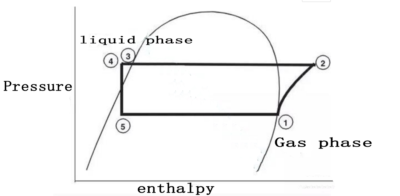
The refrigeration cycle of a screw chiller can be represented by a pressure-enthalpy diagram. The main state points are shown in the diagram, which will be used in the following discussion.
The refrigerant evaporates in the evaporator. A certain amount of liquid refrigerant enters the distributor in the evaporator cylinder, and then is distributed to the evaporator tube bundle. The refrigerant evaporates while cooling the water in the evaporation tube. The refrigerant vapor leaves the evaporator at the saturation point (state point 1).
The refrigerant vapor generated in the evaporator flows into the suction end of the compressor and enters the motor box of the compressor that is cooled by suction. The refrigerant rotates around the motor and enters the compression chamber after releasing a certain amount of cold. The refrigerant is compressed to the discharge pressure in the compressor, and the lubricating oil is drawn into the compressor for two purposes: (1) lubricate the rolling bearings, (2) seal the small gap between the two compressor rotors.

After compression, the lubricating oil and refrigerant are separated in the oil separator, and the oil-free refrigerant enters the condenser at state point 2. The baffle in the condenser makes the compressed refrigerant vapor evenly distributed in the condenser tube bundle. The cooling water flowing out of the cooling tower flows into the condenser tube to absorb heat and condense the refrigerant.
The state of refrigerant flowing out of the condenser is at 3 points. Before entering the electronic expansion valve (state 4), it enters the subcooler and then cools. The pressure drop during the expansion process causes part of the refrigerant to evaporate, and the resulting vapor-liquid mixture enters the evaporator distribution system at state point 5. Part of the flash gas during the expansion process is directed to the compressor suction port, and the liquid refrigerant is distributed along the evaporator tube bundle.
2.Appearance and component reference of screw water cooling unit


Three, common failure analysis of screw chiller
During the use of screw chillers, everyone will ask some common faults, such as high pressure faults, low pressure faults, low valve temperature faults, compressor overheating faults, communication faults, etc., but if you want to effectively solve these faults, it is better You must first understand the main working principles of screw chillers, and the most important of them are the four processes of the refrigeration cycle, which is the pressure-enthalpy diagram and the refrigeration system cycle mentioned at the beginning of this article. Understanding these are just the basics. After understanding the main working principle of screw chillers, let's analyze common failures of screw chillers for your reference.
1. High pressure failure: The compressor discharge pressure is too high, causing the high pressure protection relay to act. The compressor discharge pressure reflects the condensing pressure, the normal value should be 1.40~1.60MPa, and the protection value is set to 2.00MPa. If the pressure is too high for a long time, it will cause the compressor to run too much current, easily burn the motor, and easily cause damage to the compressor exhaust valve. Naturally, what should be done is to control the compressor exhaust pressure within a safe range. Inside!
The reasons for high voltage failure are as follows:
The cooling water temperature is too high and the condensation effect is poor;
The cooling water flow is insufficient, and the rated water flow is not reached;
The condenser is scaled or blocked;
Overcharged refrigerant;
The refrigerant is mixed with non-condensable gases such as air and nitrogen;
False alarms caused by electrical faults.
2. Low pressure failure: The suction pressure of the compressor is too low, causing the low pressure protection relay to act. The compressor suction pressure reflects the evaporation pressure, the normal value should be 0.40~0. 60MPa, the protection value is set to 0. 20MPa. If the suction pressure is low, the return air volume is small, and the refrigeration capacity is insufficient, resulting in a waste of electric energy. For the return air cooling compressor motor, the heat dissipation is poor and the motor is easily damaged! The solution is the same as the high pressure failure, try to keep the compressor within the normal pressure range.
The causes of low voltage failure are as follows:
Insufficient refrigerant or leakage;
The flow of refrigerant water is insufficient and the heat absorbed is small;
false alarm caused by electrical failure;
The outside temperature is low.
3. Low valve temperature failure: The outlet temperature of the expansion valve reflects the evaporation temperature, which is a factor affecting heat exchange. Generally, the difference between it and the outlet temperature of the refrigerant water is 5.0~6.0℃. When a low valve temperature failure occurs, the compressor will stop, and when the valve temperature rises, it will automatically resume operation with a protection value of -2.0°C.
Low valve temperature failure causes are as follows:
A small amount of refrigerant leaks, which generally manifests as a low valve temperature failure rather than a low pressure failure;
The expansion valve is blocked or the opening is too small, and the system is not clean;
The refrigerant water flow is insufficient or the evaporator is blocked;
False alarms caused by electrical faults, such as poor contact of valve temperature wires.
3.Compressor overheating failure: The thermistor is embedded in the compressor motor winding, and the resistance is generally 1kΩ. When the winding is overheated, the resistance value will increase rapidly. When it exceeds 141kΩ, the thermal protection module SSM will act to cut off the operation of the unit. At the same time, the overheating fault will be displayed and the fault indicator will be on.
4. Compressor overheating failure causes are as follows:
The compressor load is too heavy and the overcurrent is running;
Compressor overcurrent operation caused by electrical failure;
The overheating protection module M is damp or damaged, the intermediate relay is damaged, and the contacts are bad.
5. Communication failure: The computer controller controls each module through the communication line and the main interface board. The main reason for the communication failure is poor contact or open circuit of the communication line, especially the interface is damp and oxidized to cause poor contact. Electronic board or main interface board failure, improper selection of address dial switch, power supply failure can cause communication failure.
The above five failure phenomena are the most common, and understanding these failure phenomena, judgment capabilities, and solutions has an irreplaceable effect on prolonging the service life of screw chillers!
