


Figure 1: DC motor.
According to the reversible principle of DC motors, DC motors are divided into DC motors and DC generators.
According to whether there is a brush device, DC motors are divided into brushed DC motors (brush DC motors) and brushless DC motors.
According to the excitation mode, DC motors are divided into three categories: permanent magnet, separately excited and self-excited, of which self-excitation is further divided into three types: shunt excited, series excited and compound excited.
1. Reversible Principle of DC Motors
In principle, a DC motor can run both as an electric motor and as a generator, which is called the reversible principle in motor theory. When the prime mover drives the armature winding to rotate between the main magnetic poles N and S, an electromotive force is induced on the armature winding. It is rectified to DC by the brush and commutator device, and then led to the external load (or power grid) to supply power to the outside world. At this time, the motor operates as a DC generator.
If an external DC power supply is used to lead the DC current to the armature winding through the brush commutator device, the current interacts with the magnetic field generated by the main magnetic pole N.S. to generate torque, which drives the rotor to work with the mechanical load connected to it. At this time, the motor operates as a DC motor.
1.1 How DC Motors Work
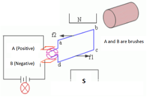
Figure 2: Working principle diagram of DC motor.
In the figure, the coil is connected to the commutator segment, which is fixed on the rotating shaft and rotates with the motor shaft. The commutator segments are insulated from each other and from the rotor shaft. The brushes A and B are fixed in space.
The DC voltage is applied to the two brush ends of the motor. The electric energy is introduced into the armature coil due to the action of the brush and the commutator, and it is ensured that the current in the coil side of the same pole is always in one direction. It ensures the direction of the electromagnetic force on the coil side of the same pole remains unchanged, which ensures that the motor can rotate continuously, so as to convert electrical energy into mechanical energy to drive the production machinery. This is the working principle of the DC motor. NOTE: The current direction in each coil side is alternating.
1.2 How DC Generators Work
As shown in the figure, when the armature is driven by the prime mover to rotate counterclockwise, the coil will induce an electric potential from cutting magnetic field lines, and the electric potential direction can be determined according to the right-hand rule. Due to the continuous rotation of the armature, the coil sides ab and cd will alternately cut the magnetic lines under the N and S poles.
The direction of the induced electromotive force in each coil side and the entire coil is alternating, so the induced electromotive force in the coil is alternating. But due to the action of brushes and commutators, the current flowing through the load is a unidirectional DC current, which is generally pulsating.
In the figure, the electromotive force put out by brush A is always the electromotive force in the side of the coil cutting the N-pole magnetic field line, and it always has positive polarity; brush B always has negative polarity. This is how a DC generator works.
2. With or without Brushes

Figure 3: Types of DC motor.
2.1 Brushless DC Motor
The brushless DC motor replaces the stator and rotor of the ordinary DC motor. The rotor is a permanent magnet to generate air-gap magnetic flux; the stator is an armature, which is composed of multi-phase windings. Structurally, it is similar to a permanent magnet synchronous motor.
The structure of the brushless DC motor stator is the same as that of an ordinary synchronous motor or an induction motor. Multiphase windings (three-phase, four-phase, five-phase, etc.) are embedded in the iron core. The windings can be connected in a star or delta shape, and are respectively connected with the power tubes of the inverter for reasonable commutation.
The rotor is mostly made of rare earth materials with high coercivity and high remanence density, such as samarium cobalt or neodymium iron boron. Due to the different positions of the magnetic materials in the magnetic poles, it can be divided into surface magnetic poles, embedded magnetic poles and annular magnetic poles. Since the motor body is a permanent magnet motor, it is customary to call the brushless DC motor also a permanent magnet brushless DC motor.

Figure 4: Working principle diagram of brushless DC motor.
2.2 Brushed DC Motor
Brushed DC motor stator has winding type or permanent magnet type, and the rotor is armature winding. The two brushes (copper brushes or carbon brushes) of the brushed motor are fixed on the back cover of the motor through the insulating seat, and it directly introduces the positive and negative poles of the power supply into the commutator of the rotor, and the commutator is connected to the coil on the rotor. The 3 coils with alternating polarities and the 2 magnets fixed on the shell form a force to rotate.
Since the commutator and the rotor are fixed together, and the brush and the casing (stator) are fixed together, when the motor rotates, the brush and the commutator constantly rub and generate a lot of resistance and heat. Therefore, the efficiency of the brushed motor is very low and the loss is very large. But it also has the advantages of simple manufacture and low cost.

Figure 5: Working principle diagram of brushed DC motor.
3. Excitation Method
The excitation mode of the DC motor refers to the problem of how to supply power to the excitation winding (field winding), and generate the excitation electromotive force to establish a main magnetic field. The following will introduce several types of DC motors including separately-excited DC motors, shunt DC motors, series DC motors, and compound DC motors.
3.1 Separately Excited DC Motor

Figure 6: Wiring diagrams of separately excited DC motor and DC shunt motor.
A DC motor in which the excitation winding is not connected to the armature winding and is powered by another DC power source is called separately excited DC motor. Permanent magnet DC motors can also be regarded as separately excited DC motors.
3.2 DC Shunt Motor
The excitation winding of the DC shunt motor (shunt DC motor, shunt wound DC motor) is connected in parallel with the armature winding. As a shunt generator, the terminal voltage emitted by the motor itself supplies power to the excitation winding; as a shunt motor, the excitation winding and the armature share the same power supply. A shunt DC motor is the same as a separately excited DC motor in terms of performance.
3.3 DC Series Motor

Figure 7: Wiring diagrams of DC Series Motor and DC Compound Motor.
The excitation winding of the DC series motor (series DC motor, series wound DC motor) is connected in series with the armature winding, and then connected to the DC power supply. The excitation current of such a DC motor is the armature current.
3.4 DC Compound Motor
The DC compound motor (compound DC motor, compound wound DC motor) has two excitation windings, shunt excitation and series excitation. If the magnetomotive force generated by the series excitation winding is in the same direction as that of the shunt excitation winding, it is called cumulative compound excitation. If the two magnetomotive forces are in opposite directions, it is called differential compound excitation.
DC motors with different excitation methods have different characteristics. In general, the main excitation modes of DC motors are shunt excitation, series excitation and compound excitation, and those of DC generators are separately excitation, shunt excitation and compound excitation.
4. DC Motor vs AC Motor
What is the difference between a DC motor and an AC motor?
1.Different types of input power: AC motors use AC power, while DC motors use DC power.
2.Different uses: DC motors are mainly used for power machinery or other equipment with a wide range of speed regulation (smooth speed regulation is required), while AC motors are mainly used for those whose speed regulation range is not too large.
Related Info
Advantages, disadvantages and applications of linear motorsTop 10 Brands of Linear Motors
What is DC Motor and How Does It Work?
Types of Linear Motors
What is Linear Motor and How Does It Work?
