


Figure 1: DC motor.
A DC motor (direct current motor) refers to a rotating electrical machine that can convert direct current electrical energy into mechanical energy (DC motor) or convert mechanical energy into direct current electrical energy (DC generator). It is a motor that can realize the mutual conversion of DC electrical energy and mechanical energy. When it operates as a motor, it is a DC motor, which converts electrical energy into mechanical energy; when it operates as a generator, it is a DC generator, which converts mechanical energy into electrical energy.
1. Structure of DC Motor
The structure of the DC motor should be composed of two parts: the stator and the rotor.
The stationary part of the DC motor is called the stator. The main function of the stator is to generate a magnetic field, which is composed of frame, main pole, commutating pole, end cover, bearing and brush device.
The part that rotates during operation is called the rotor. Its main function is to generate electromagnetic torque and induced electromotive force. It is the hub for the energy conversion of the DC motor, so it is usually called the armature, which consists of rotor shaft, armature core, armature winding, commutator and fan.
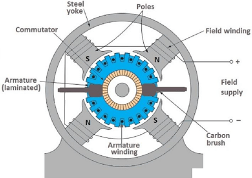
Figure 2: Structure of DC motor.
1.1 Stator
(1) Main pole
The main pole is used to generate the air-gap magnetic field, and make the air-gap flux density on the surface of the armature distributed along the space according to a certain waveform. The main pole includes the main pole core and the excitation winding. The main pole core is made by lamination of 1mm ~ 1.5mm thick low carbon steels. The excitation winding is made of round or rectangular pure copper insulated magnet wire. The excitation windings of each pole are connected in series to ensure equal current in the excitation windings of each main pole.
A large DC motor is slotted on the pole shoe, and the compensating winding is embedded in the slot, which is connected in series with the armature winding to offset the armature reaction magnetomotive force within the range of the pole shoe, thereby reducing the distortion of the air-gap magnetic field, improving the commutation, and increasing the reliability of motor operation.
(2) Commutating pole
The function of the commutation pole is to improve the commutation and reduce the commutation spark that may be generated between the brush and the commutator when the motor is running. It is generally installed between two adjacent main poles, consisting of commutation pole core and commutation pole winding. The commutating pole winding is made of insulated wire and is wound on the commutating pole core. The number of commutating poles is equal to that of the main pole. Generally, when the motor capacity exceeds 1KW, the commutating pole should be installed.

Figure 3: Main poles and commutating pole.
(3) Frame
The housing of the motor stator is called the frame, which has two functions:
One is to fix the main pole, commutating pole and end cover, and to support and fix the entire motor.
Second, the frame itself is also a part of the magnetic circuit, which constitutes the magnetic path between the magnetic poles, and the part which the magnetic flux passes through is called the yoke. In order to ensure that the frame has sufficient mechanical strength and good magnetic permeability, it is generally made of steel castings or welded steel plates.
(4) Brush device
Brush devices are used to put in or out DC voltage and DC current. The brush device consists of brush, brush holder, brush rod and brush rod seat. The brush is placed in the brush holder and pressed with a spring, so that there is a good sliding contact between the brush and the commutator. The brush holder is fixed on the brush rod, and the brush rod is mounted on the annular brush rod seat, which must be insulated from each other. The brush rod seat is installed on the end cover or the bearing inner cover, the circumferential position can be adjusted, and it should be fixed after adjustment.

Figure 4: Carbon brushes.
1.2 Rotor
(1) Armature core
The armature core is the main part of the main magnetic circuit, and is used to embed the armature winding. Generally, the armature core is composed of punched laminations made of 0.5mm thick silicon steel sheets to reduce the eddy current loss and hysteresis loss generated in the armature core when the motor is running. The stacked core is fixed on the rotating shaft or rotor bracket. The outer circle of the iron core is provided with an armature slot, and the armature winding is embedded in the slot.
(2) Armature winding
The function of the armature winding is to generate electromagnetic torque and induced electromotive force, and it is the key component of the energy conversion of the DC motor. It is made up of many coils connected according to certain rules, and the coils are wound with high-strength enameled wire or glass wire wrapped flat copper wire.

Figure 5: Armature winding.
(3) Commutator
In the DC motor, the commutator is used in conjunction with the brush, which can convert the external DC power into the alternating current in the armature coil, so that the direction of the electromagnetic torque is constant. In the DC generator, the commutator, equipped with brushes, can convert the alternating electromotive force induced in the armature coil into the direct current electromotive force put out from the positive and negative brushes. The commutator is a cylinder composed of many commutator segments, and the commutator segments are insulated with mica sheets.
(4) Rotary shaft
The rotating shaft plays the role of supporting the rotation of the rotor, and needs to have a certain mechanical strength and rigidity, and is generally made of round steel.
2. How DC Motor Works
To understand how a DC motor works, let's start with a simple case where a rectangular wire loop is placed inside the north and south poles of a permanent magnet. When current flows through the coil, it creates a magnetic field around the coil. This magnetic field interacts with the pre-existing magnetic field of the permanent magnet, creating a repulsive force, the direction of which can be determined using Fleming's left-hand rule.
The working principle of the DC motor is to connect the DC power supply to the armature winding through the brush, so that a current flows through the armature conductors. There is a magnetic field inside the motor, and the current-carrying rotor (that is, the armature) conductor will be subjected to an electromagnetic force f (left-hand rule). The electromagnetic force generated by all conductors acts on the rotor, causing the rotor to rotate at n (revolutions per minute), so that the mechanical load is dragged.
When the coil on the rotor is parallel to the magnetic field and continues to rotate, the direction of the magnetic field will change, because at this time the brushes at the end of the rotor are in contact with the commutator segments alternately. The direction of the current on the coil also changes, but the direction of the Lorentz force generated remains the same, so the motor can keep turning in one direction.
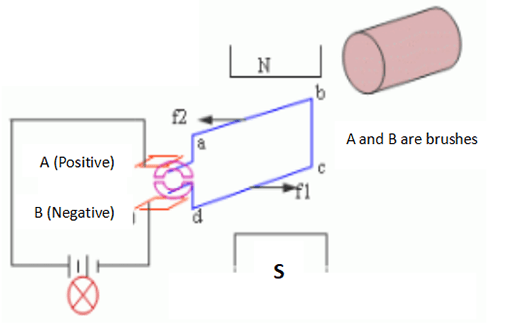
Figure 6: Working principle diagram of DC motor.
3. Characteristics of DC Motor
(1)Good speed regulation performance. The so-called "speed regulation performance" refers to the artificial change of the motor speed according to the needs of the motor under a certain load condition. The DC motor can achieve uniform and smooth stepless speed regulation under heavy load conditions, and the speed regulation range is wide.
The most common methods of adjusting the speed of DC motors (ways to DC motor speed control) include changing the excitation current, changing the armature voltage, etc.
(2)large starting torque. Therefore, all machinery that starts under heavy load or requires uniform adjustment of speed, such as large reversing rolling mills, winches, electric locomotives, trams, etc., are driven by DC motors.
4. How to Change Rotation Direction of DC Motor
There are two ways to change the direction of rotation of a DC motor:
One is the armature reverse connection method, that is, the polarity of the terminal voltage of the excitation winding is kept unchanged, and the motor is reversed by changing the polarity of the terminal voltage of the armature winding.
The second method is the reverse connection of the excitation winding, that is, the polarity of the voltage at the end of the armature winding is kept unchanged, and the direction of the motor is adjusted by changing the polarity of the voltage at the end of the excitation winding.
When the voltage polarities of the two are changed at the same time, the rotation direction of the motor does not change.
Separately excited DC motors and DC shunt motors generally use the armature reverse connection method to realize forward and reverse rotation. The reason why it is not suitable to use the reverse connection of the excitation winding to achieve forward and reverse rotation is that the number of turns of the excitation winding is large and the inductance is large. When the excitation winding is reversed, a large induced electromotive force will be generated in the excitation winding. This will damage the insulation of the gate and the excitation winding.
The DC series motor should adopt the reverse connection of the excitation winding to realize the forward and reverse rotation because the voltage across the armature of the DC series motor is relatively high, while the voltage at both ends of the excitation winding is very low, and the reverse connection is easy. Electric locomotives often use this method.
Related Info
Advantages, disadvantages and applications of linear motorsTop 10 Brands of Linear Motors
What are the Advantages of Synchronous Reluctance Motor?
Types of Linear Motors
What is Linear Motor and How Does It Work?
