


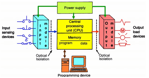
Figure 1: Structure of PLC.
(Go to Okmarts and pick the PLC you need)
1. Overview
PLC I/O is the part of the PLC that connects the brain of the PLC, the CPU, to the outside world, the machines. In a PLC system there will usually be dedicated modules for inputs and dedicated modules for outputs. An input module detects the status of input signals such as push-buttons, switches, temperature sensors, etc.. An output module controls devices such as relays, motor starters, lights, etc.
2. Discrete I/O
The most common type of PLC I/O is discrete I/O. Sometimes discrete I/O is referred to as digital I/O. The concept is simple, discrete I/O are signals that are either on or off.

Figure 2: Discrete input device ( circuit breaker ).
Some examples of discrete input devices are light switches, button and door switches, water level switches, etc. Examples of discrete output devices are lamps, relays, and motor starters. Some discrete outputs will be water injection valves, drain valves and heating elements.
Some specific applications of PLC discrete input devices would be circuit breakers or closed circuit breakers, running or stopped generators, conveyor position sensors, or tank level sensors. Some specific applications of discrete outputs include closing or opening circuit breakers, starting or stopping generators, opening or closing water valves, or turning on and off alarm lights.
3. Analog I/O
The other common form of PLC I/O is analog I/O. Analog I/O refers to signals that have a range of values much greater than just 1 or 0. For instance, an analog signal could produce a voltage anywhere in the range of 0 – 10 VDC. The signal could be 2 V, 3 V, 8.5 V, etc. In the PLC world, analog input modules usually measure analog inputs in one of the following forms: -10 to 10 VDC, 0 – 10 VDC, 1 to 5 VDC, 0 to 1 mA, or 4 – 20 mA. Basically the analog input module either measures voltage or current from the input device.
An analog signal that most of us are familiar with is the light dimmer. As you adjust the dimmer knob or slider, the light will get either dimmer or brighter depending on the direction of the adjustment. Similarly an analog input into the PLC can increase or decrease in very small increments and the PLC can produce an analog output that acts the same way.
Some real-world examples of analog inputs in a industrial environment would include engine temperature sensors (RTDs, thermocouples, etc.), oil pressure sensors and weight scales. A temperature sensor might report a temperature range of -50 to 150 degrees C corresponding to 4-20 mA. A weight scale might report a range of 0 to 1000 lb corresponding to 0 to 10V. And so on and so forth. Analog outputs can be used to control the power output on a generator, the position of a needle on an analog pressure meter, and much more. A 0-3 VDC analog output might be used to drive a generator from 0 – 2000 kW or a 4-20 mA analog output could be used to drive temperature gauge from -20 to 200 degrees F. As you can see there are many possibilities for applications of analog inputs and outputs!

Figure 3: A switch of the light dimmer.
4. Industrial Communication
In most PLC systems, discrete I / O and analog I / O account for the majority of I / O. There are many industrial communication protocols: Modbus, DNP, BACnet, ControlNet, Ethernet / IP, etc. Modbus is one of the oldest industrial communication protocols. It is still widely used in many devices and PLC because of its simplicity and wide acceptance. So what does this have to do with PLC I / O? Many equipment, such as PLC, digital instrument, SCADA system, VFD and generator set controller, are designed with internal data diagram of input and output points. The equipment designer can decide how to allocate data. The master device can also write data to the slave device. For example, a programmable logic controller (PLC) can be set as a Modbus host to write data to start, stop, or change the speed of a variable frequency drive (VFD).
Though all communications protocols work differently they are all designed to do basically the same thing. Industrial communications devices read and write analog or discrete values from and to other PLCs/devices without the need for hardwiring every single input and output point between the PLCs/devices.
As you can see, not only can you connect hard-wired inputs and outputs to your PLC, but you can also read input data from and write output data to devices over Modbus and other industrial communications protocols. This versatility allows most PLCs/PACs to interface with almost any device in an industrial environment.
5. Conclusion
In this post we looked at discrete I/O, analog I/O and industrial communications protocols. Those three items are responsible for executing all the wishes of the PLC CPU. The CPU looks at data from discrete input modules, analog input modules, and Modbus slaves (or other industrial communications devices). The CPU then performs logic on that input data and activates/deactivate discrete output modules, analog output modules or Modbus slaves. If you can can put PLC I/O into these three categories in your head (discrete, analog, communications) then you will have a great foundation for knowing how to get data in and out of a PLC.
Related Info
How to clean automobile solenoid valveWorking principle of 5 kinds of solenoid valves
10 matters when installing water solenoid valve
