


Figure 1: Someone is using the VFD.
The Variable Frequency Drive (VFD) is a device widely used to convert the constant voltage of an autonomous AC power source into a variable voltage for controlling the torque and speed of the motor. They are ideal for motors that drive loads on mechanical equipment. A VFD offers higher efficiency than simple inline motors, as well as a degree of control not available with simple drive motors. These factors can save energy costs, improve production performance and extend motor life.
Challenges of VFD
The VFD is also known as VSD and ASD. Troubleshooting and testing are usually performed by experts using a variety of test instruments, including oscilloscopes, multimeters, or other tools. These tests may involve some degree of trial and error using the ancient method of elimination. Because of the complexity of the motor system, testing is usually done once a year unless the system starts to fail.
Given that equipment often lacks or has an incomplete record, it’s difficult to determine where to start testing. This includes recording specific tests and measurements performed previously, the completed work, or the individual components after adjustments. Advances in testing technology have solved some of the challenges.
New instruments such as the Fluke Motor Drive Analyzer (MDA-510 and MDA-550) are designed to make VFDs more efficient, and to document the process step by step. These reports can be saved and compared with subsequent test results for a more complete understanding of the motor driver's maintenance history.
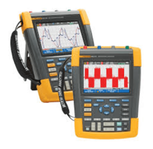
Figure 2: The Fluke Motor Drive Analyzer.
Simpler Troubleshooting Method for VFD
These advanced motor driver analyzers combine the capabilities of instruments, handheld oscilloscopes, and recorders with the guidance of a skilled instructor, using on-screen prompts, clear setup drawings, and step-by-step instructions written by motor driver experts to guide you through basic testing. This new approach to breaking down and simplifying complex tests enables experienced motor drive specialists to work quickly and confidently to get important and detailed information. It also provides a faster way for inexperienced technicians to start the motor driver analysis.
By implementing a standard set of tests and measurements at key points within the system, the root cause of motor drive system failure can be found or routine preventive maintenance checks are performed. Being started at the power input, key tests are performed throughout the system using different measurement techniques and evaluation criteria, and are ended at the output.
Basic Tests for VFD Troubleshooting
You should note that Fluke Motor Drive Analyzer guides you through these tests and automatically performs many of the required calculations so that you will be satisfied with the results. In addition, you can save data to a report at any test point, so you can upload the document to a computerized maintenance management system (CMMS) or share it with colleagues or consulting experts.
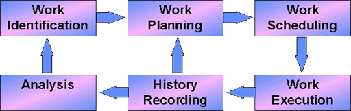
Figure 3: How to implement the computerized maintenance management system.
Before each test using Fluke Motor Drive Analyzer, you can simply connect the test probes according to the chart, and then press next.
Drive Input
To determine whether there is any distortion, interference, or noise in the driver feed circuit that could affect the grounding of the power supply, you should first analyze the power supply of the motor drive.
* Test
Comparing the nominal rated voltage of the drive with the actual supply voltage can help you to quickly check whether the value is within the acceptable limited range. More than 10% above this range indicates a problem with the power supply voltage. You should determine if the input current is within the maximum rated range and if the wire specifications are appropriate.
You should compare the measured frequency with the specified frequency. Frequency differences in excess of 0.5 Hz may cause problems.
You should examine whether the harmonic distortion is acceptable. You can visually inspect the waveform shape, or view the harmonic spectrum screen that shows both total harmonic distortion and individual harmonics. For example, a flat-top waveform may indicate a nonlinear load connected to the same feed circuit. If the total harmonic distortion (THD) exceeds 6%, it may fail.
You should check the voltage imbalance at the input terminals to ensure that the phase imbalance is not too high (less than 6%-8%) and that the phase rotation is correct. A voltage imbalance reading indicates a phase break. Readings exceeding 2% can cause voltage gaps and drive overload fail-safe trips or interfere with other devices.
Through a current imbalance test, you can find a driver rectifier problem due to the excessive imbalance. A current imbalance reading of more than 6% may indicate a problem with the motor driver's inverter.
DC Bus
The AC - DC conversion within the VFD is critical. For achieving optimal driver performance, the voltage must be correct, and adequate filter, low ripple levels are kept. High ripple voltages may mean faulty capacitors or incorrect specifications of the connected motor. The recording function of the Fluke MDA-500 Series Motor Drive Analyzer dynamically checks the performance of the DC bus in the working mode under load. You can also use Fluke ScopeMeter® Test Tool or an advanced multimeter for this test.
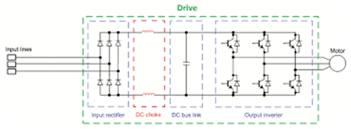
Figure 4: A DC bus.
* Test
You should determine whether the DC bus voltage is proportional to the peak input line voltage. Except for controllable rectifiers, the voltage should be approximately 1.31 to 1.41 times the RMS line voltage. Low DC voltage reading can cause the drive to trip, which can be caused by low input power voltage or input voltage distortion (such as flat top).
You check the line voltage peak amplitude for any distortion or error. This can lead to overvoltage or undervoltage errors. A DC voltage reading with a difference of +/-10% from the nominal voltage may indicate a fault.
You should determine if the peak of the AC ripple has different repeating levels. After the AC - DC conversion, a small AC ripple component is retained on the DC bus. Ripple voltages in excess of 40 V may be caused by capacitor failures or driver ratings that are too small for the connected motor or load.
VFD Output
Testing the driver output is crucial for the proper operation of the motor and can provide clues to problems in the driver circuit.
* Test
You should determine if the voltage and current are within limits. High output currents may heat the current, thus reducing the insulation life of the stator.
You can check the voltage/frequency ratio (V/Hz) to ensure that it is within the specified limits of the motor. High ratios may overheat the motor, while low ratios cause the motor to lose torque.
Stable frequencies and unstable voltages may show that there are DC bus problems, and unstable frequencies and stable voltages may indicate IGBT problems. Both frequency and voltage instability will indicate possible failures of the speed control circuit.
When you check the drive output, it is important to measure the ratio of voltage and frequency (V/F) and voltage modulation. When the V/F ratio is measured too high, the motor may overheat. If the V/F ratio is low, the connected motor may not be able to provide the required torque on the load, resulting in insufficient execution of the intended process.
Check for voltage modulation by using phase to phase measurements. High voltage peaks may damage motor winding insulation and cause drive trips. Voltage peaks exceeding the nominal voltage by more than 50% can cause problems.
You can check the sharpness of the switching pulse in the driver reading indicator. The rise time or steepness of the pulse is indicated by a dV/dt reading (the rate of change of voltage over time), which should be compared to the specified insulation value of the motor.
You should test the switching frequency of phase to DC. After identifying potential problems with electronic switches or grounding, it can be failed when the signal floats up and down.
The measurement of voltage imbalance is best carried out under full load conditions. Voltage imbalance should not exceed 2%. Voltage imbalance can cause current imbalance, resulting in overheating of the motor winding.
Causes of imbalance may include driver circuit failure. If one phase fails, it is called "single-phase operation", which can heat up the motor, prevent it from starting after shutdown, greatly reduce efficiency, and can damage the motor and the connected load.
When you measure the current imbalance for three-phase motors, it should not exceed 10%. A large imbalance at a low voltage may indicate the short-circuit in the motor windings or in phase to ground. The large imbalance may also lead to driving tripping, extremely high motor temperature and burned windings.
Motor Input
Supplying voltage to the motor input terminals is critical, as is the proper choice of wiring between the drive and the motor. Incorrect wiring choices can result in drive and motor damage due to excessive voltage peaks. These tests are essentially the same as the drive output tests described above.
* Test
You should check that the current at the terminals is within the motor rating range. Excessive current can cause the motor to overheat and shorten the life of the stator insulation, leading to premature motor failure.
Voltage modulation helps identify high voltage peaks to the ground that may damage the insulation of the motor.
Voltage imbalance can seriously affect the service life of the motor and maybe a sign of inverter failure. This can lead to a voltage gap and cause the overload fail-safe to trip.
A current imbalance may indicate a voltage imbalance or drive rectifier problem.
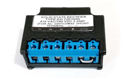
Figure 5: A rectifier.
Motor Shaft Voltage
The voltage pulse from the motor drive will be coupled between the motor stator and the rotor, resulting in a voltage on the rotor shaft.
When this rotor shaft voltage exceeds the insulation voltage of the bearing grease, a flashing current may occur, leading to pitting and grooving of the motor bearing ring. This damage may lead to premature motor failure.
* Test
You should measure the voltage between the motor frame and the drive shaft. For example, the MDA-550 provides a carbon fiber brush probe for this purpose. The test easily detects the presence of destructive flashover currents, while the pulse amplitude measurement and event count feature lets you take action before a failure occurs.
