


Figure 1: Graphic card with a cooling fan.
The cooling fan must be familiar to everyone. Computers, water dispensers, refrigerators, air conditioners, air purifiers, automobiles, etc. will have its figure inside, and it is a popular cooling device in many industries. How much do you know about the basics of cooling fans? What is its structure, working principle, or performance of various types of cooling fans?
1. Cooling Fan Structure
The rotation process of the cooling fan is a process in which the rotating electromagnetic field generated by the electrification of the stator coil and the permanent magnetic ring pressed into the fan blade repel each other. The cooling fan is mainly composed of four parts: the rotor, the stator, the motor, and the outer frame.

Figure 2: Structural diagram of common cooling fan.
1.1 Composition of Brushless DC Motor
It consists of a permanent magnet rotor, a multi-pole winding stator, a position sensor, and an electronic commutation drive control circuit.

Figure 3: The internal structure of the cooling fan.
1.2 Rotor Composition
It is composed of motor casing + magnet ring + shaft core + fan blades. Among them, the fan blades are used to
create air flow, and the shaft core is to support and balance the rotation of the fan blades.
A magnet ring is an object with residual magnetism. After being magnetized by a strong magnetic field, the object
still maintains magnetic properties when there is no external magnetic field excitation, that is, like poles repel
each other and unlike poles attract each other. The outer frame of the magnetic ring (the motor casing) is used to
fix the magnetic ring.

Figure 4: Cooling fan impeller structure.
1.3 Stator Part
The stator is composed of enameled wire + plastic-coated silicon steel sheet + bearing + Hall sensor detection + drive circuit board + bearing. The role of the bearing is to increase the speed, reduce friction, and ensure that the fan can run for a long time. The support spring is used to separate the bearing from the balance shaft. The retaining ring is used to secure the whole rotating part.

Figure 5: Cooling fan motor structure.
1.4 Outer Frame
The outer frame part of the cooling fan mainly functions as the supporting and airflow guiding.
2. How the Cooling Fan Works
According to Ampere's right-hand rule, when a current passes a conductor, a magnetic field will be generated around it. If the conductor is placed in another fixed magnetic field, an attraction or repulsion will be generated, causing the object to move.

Figure 6: Cooling fan working principle diagram.
Inside the cooling fan, a rubber magnet is attached, surrounding the silicon steel sheet. Two sets of coils are
wound around the stator core, and a Hall sensor component is used as a synchronous detection device to control a set
of circuits.
This circuit makes the two sets of coils wound around the stator core work alternately, so the silicon steel sheet
produces different magnetic poles, which generate repulsive force with the rubber magnet. When the attraction and
repulsion force is greater than the static friction of the fan, the fan blades will rotate naturally.
3. Cooling Fan Speed
The speed of the cooling fan refers to the number of times the fan blades rotate per minute, and the unit is rpm.
The fan speed is determined by the number of turns of the inner coil of the motor, the operating voltage, the number
of fan blades, the inclination angle, the height, the diameter and the bearing system.
The rotational speed of the cooling fan can be measured through an internal rotational speed signal, or can be
measured externally. The external measurement is to use other instruments (such as a hot wire anemometer) to see how fast the fan is
spinning, and the internal measurement can be directly checked in the BIOS or through software.
As the ambient temperature changes, fans with different speeds are sometimes required to meet the demand. Some fans
can automatically control the speed of the fan according to the current operating temperature (such as the
temperature of the heat sink). If the temperature is high, the speed will be increased, and if the temperature is
low, the speed will be reduced.

Figure 7: Hot wire anemometer.
4. Cooling Fan Air Volume
The air volume of the cooling fan refers to the total volume of air discharged or taken in by the air-cooled
radiator fan per minute. If it is calculated in cubic feet, the unit is CFM. If it is calculated by cubic meter, it
is CMM. The air volume unit often used in radiator products is CFM (about 0.028 cubic meters per minute).
In the case of the same heat sink material, the air volume is the most important indicator to measure the heat
dissipation capacity of the air-cooled heat sink. Obviously, the larger the air volume of the radiator, the higher
the cooling capacity of the cooling fan. This is because the heat capacity ratio of the air is constant, and a
larger air volume, that is, more air per unit time can take away more heat.
Of course, under the same air volume, the heat dissipation effect is related to the flow mode of the wind. Air
volume and wind pressure are two relative concepts.
5. Control Signal of Cooling Fan
The most common is the 2-wire fan. The 2 wires are power wire (red) and ground wire (black). A 2-wire fan runs at full speed when it is powered on, and the motherboard CPU cannot control the fan speed, nor does it know whether the fan is currently running.

Figure 8: 2-wire fan.
A little more advanced is the 3-wire fan. The 3 wires are power wire (red), ground wire (black), speed measuring wire (yellow).

Figure 9: 3-wire fan.
The speed measuring line is an output line, which outputs a signal to the CPU to tell the current fan speed.
Finally, let's talk about the 4-wire fan. As shown in the figure below, this is also the most commonly used
speed-adjustable fan.

Figure 10: 4-wire fan.
The 4-wire fan has one more control signal than the 3-wire fan, and the CPU outputs PWM waves (adjustable duty cycle) to control the speed of the fan.
6. Characteristics of 4 Types of Cooling Fans
The following mainly introduces the classification according to the different directions of the airflow in and out of the cooling fan.
6.1 Axial Flow Fan

Figure 11: Axial fan.
The blades of an axial fan push air to flow in the same direction as the shaft (parallel direction). The impeller of
the axial flow fan is somewhat similar to the propeller. When it is working, the flow direction of most of the
airflow is parallel to the shaft.
Axial fans consume the least power when the inlet airflow is free air at zero static pressure. When running, the
power consumption will increase with the rise of the air flow back pressure.
Since the axial flow fan features compact structure, space saving, and easy installation, it is widely used. Axial
fans are usually installed on the cabinet of electrical and electronic equipment, and sometimes integrated on the
motor.
The main characteristics of axial flow fans are high flow rate, and medium wind pressure, and they meet the heat
dissipation requirements of the general environment.
6.2 Cross-Flow Fan

Figure 12: Cross-flow fan.
Cross-flow fans can generate large-area airflow and are usually used to cool large surfaces of equipment. The inlet
and outlet of this fan are perpendicular to the shaft.
The cross-flow fan uses a relatively long barrel-shaped fan impeller to work. The diameter of the barrel-shaped fan
impeller is relatively large. Because of the large diameter, it is possible to use a relatively low speed on the
basis of ensuring the overall air circulation, thereby reducing the noise caused by high-speed operation. It is
mostly used in elevators, air conditioners, automobiles and other equipment.
The main characteristics of cross-flow fans are low flow rate, low wind pressure, and large heat dissipation area.
6.3 Mixed Flow Fan
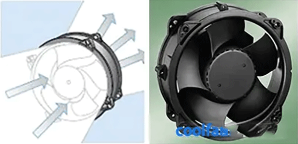
Figure 13: Mixed flow fan and the airflow direction diagram.
The mixed flow fan is also called the diagonal flow fan. This kind of mixed flow fan is no different from the axial
flow fan in appearance. In fact, the air intake direction of the mixed flow fan is along the shaft, but the air
outlet direction is along the diagonal direction between the shaft and the line perpendicular to the shaft.
Due to the conical shape of the impeller and the housing of this fan, the wind pressure is relatively high.
The main characteristics of mixed flow fans are high flow rate and relatively high wind pressure to achieve better
heat dissipation
6.4 Centrifugal Fan

Figure 14: Centrifugal fan.
When the centrifugal fan works, the blades push the air to flow in a direction perpendicular to the shaft (that is,
radial direction). The air intake direction is along the shaft, and the air outlet direction is perpendicular to the
shaft direction.
In most cases, the cooling effect can be achieved by using an axial fan. However, sometimes if the airflow needs to
be rotated 90 degrees to discharge or a larger wind pressure is required, a centrifugal fan must be used.
The main characteristics of centrifugal fans are changing the flow direction of the wind, relatively limited flow
rate, and high wind pressure.
