


Figure 1: A surge protector.
Surge protector is composed of five parts: discharge gap, discharge tube, varistor, suppression diode and choke coil which includes at least one nonlinear voltage limiting element. Today, let's focus on the working principle of these components.
1. Discharge Gap
The discharge gap is generally composed of two metal rods with a certain gap exposed to the air. One metal rod is connected with the power phase line L1 or zero line (n) of the required protective equipment, and the other metal rod is connected with the grounding wire (PE). When the instantaneous overvoltage strikes, the gap is broken down and part of the overvoltage charge is taken into the earth avoiding the voltage rise on the protected equipment. The distance between the two metal rods of the discharge gap can be adjusted as needed, and the structure is relatively simple. Its disadvantage is poor arc extinguishing performance. The improved discharge gap is angular gap and its arc extinguishing function is better than the former. It extinguishes the arc by the action of electric power F of the circuit and the rising action of hot gas flow.
2. Discharge Tube

Figure 2: A discharge tube of the surge protector.
The gas discharge tube is composed of a pair of cold cathode plates separated from each other and encapsulated in a glass tube or ceramic tube filled with a certain amount of inert gas (AR). In order to improve the trigger probability of the discharge tube, there is also a trigger aid in the discharge tube. This kind of discharge tube has two pole type and three pole type,
3. Varistor
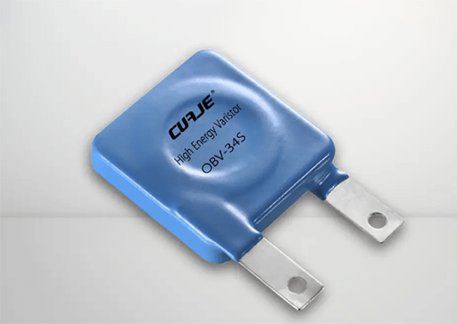
Figure 3: A varistor of the surge protector.
Varistor is a metal oxide semiconductor nonlinear resistor with ZnO as the main component. When the voltage acting on both ends reaches a certain value, the resistance is very sensitive to the voltage. Its working principle is equivalent to the series and parallel connection of multiple semiconductor p-n. Varistor is characterized by good nonlinear characteristics (I = CU α Nonlinear coefficient in α), Large current capacity (~ 2KA / cm2), small normal leakage current (10-7 ~ 10-6A), low residual voltage (depending on the working voltage and current capacity of the varistor), fast response time to instantaneous overvoltage (~ 10-8s) and no freewheeling.
The maximum reference voltage of the varistor should be determined by the withstand voltage of the protected electronic equipment. The residual voltage should be lower than the loss voltage level of the protected electronic equipment (Ulma) max ≤ Ub / K, where K is the residual voltage ratio and Ub is the loss voltage of the protected equipment.
4. Suppression Diode

Figure 4: Suppression diodes.
The suppression diode has the function of clamping and voltage limiting. It works in the reverse breakdown region. Because it has the advantages of low clamping voltage and fast action response, it is especially suitable to be used as the last protection element in multi-level protection circuit. The volt ampere characteristics of the suppression diode in the breakdown region can be expressed by the following formula: I = CU α, In the above formula α Is the nonlinear coefficient for zener diodes α= 7 ~ 9, in avalanche diode α= 5~7. For Zener Diodes α= 7 ~ 9, for avalanche diode α= 5~7.
5. Choke Coil

Figure 5: A choke coil.
Choke coil is a common mode interference suppression device with ferrite as the magnetic core. It consists of two coils with the same size and a coil symmetrically wound on the same ferrite ring magnetic core to form a four terminal device. It is used to suppress the large inductance of common mode signal, but it has little effect on the small leakage inductance of differential mode signal. The choke coil used in the balanced line can effectively suppress the common mode interference signal (such as lightning interference). But it has no effect on the differential mode signal normally transmitted by the line.
Related Info
How to properly ground the electromagnetiflowmeter under different installation conditionsWhy electromagnetic flowmeter needs grounding
How does electromagnetic flowmeter work
