


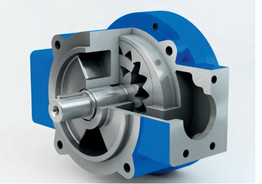
Figure 1: The cutaway view of the internal gear pump.
1. Structural Features of Gear Pump
1. Good self-priming performance;
2. The direction of suction and discharge depends entirely on the rotational direction of the pump shaft;
3. The flow rate of the gear pump is continuous and not large, but there is pulsation and large noise; the pulsation rate is 11%~27%, and its non-uniformity is related to the number and shape of gear teeth. The non-uniformity of the helical gear is smaller than that of the spur gear, and the herringbone gear is smaller than that of the helical gear. The smaller the number of teeth, the greater the pulsation rate;
4. Theoretical flow is determined by the size of the working parts and the gear pump speed, and has nothing to do with the discharge pressure; the discharge pressure is related to the pressure of the load;
5. Simple structure, low price, few wearing parts (no need to set suction and discharge valve), impact resistance, reliable operation, and able to be directly connected with the electric motor (no need to set a reduction device);
6. There are many friction surfaces, so it is not suitable to transport the liquid containing solid particles, but appropriate to convey the oil.
2. How Gear Pumps Work
2.1 Working Principle of External Gear Pump
Most of the involute external gear pumps use a pair of gears with the same parameters, and special pumps use three or more gears.
The figure below shows the working principle of an involute external gear pump using a pair of gears. The drive gear 4 and the driven gear 7 with the same geometric parameters engage in the sealed space formed by the housing 1 and the side cover and the like. The housing 1, the side cover and space between gear teeth of the gears form a number of sealed working chambers 5.

Figure 2: Working principle diagram of involute external gear pump.
1—Shell; 2—Key; 3—Drive shaft; 4—Drive gear; 5—Sealed working chamber; 6—Oil suction chamber; 7—Driven gear; 8—Oil tank; 9—Pressure oil chamber
The clearance between the tooth top of the gear and the surface of the inner hole of the housing and between the end face of the gears and the side cover is very small, and the meshing teeth is in close contact, which acts as a seal and separates the oil suction area from the oil discharge area.
When the prime mover drives the drive gear 4 and the driven gear 7 to run in the direction shown in the figure through the transmission shaft 3, the volume between the teeth becomes larger in the oil suction chamber 6 due to the disengagement of the gear teeth, and a vacuum is formed to suck oil from the oil tank 8.
The sucked oil is carried to the oil discharge chamber 9 by the rotating teeth; in this chamber, the oil is pressed to the system due to the reduction of the inter-teeth volume.
The pump shaft rotates once, and each working chamber sucks and discharges oil once. When the prime mover drives the pump to run continuously, the pump discharges oil continuously and periodically.

Figure 3: External gear pump.
The structural characteristics of the external gear pump: the change of the closed volume formed by the teeth and the pump casing is used to complete the function of the pump. There is no need for a flow distribution device, can not achieve variable displacement, and has the simplest structure, low price, large radial load.
2.2 Working Principle of Internal Gear Pump
There are two types of internal gear pumps: involute tooth profile (Crescent) and cycloidal tooth profile (Grout). Their structures are shown in the figure below. The working principle and main features of these two types of internal gear pumps are the same as those of external gear pumps.
 and cycloidal gear pump-min.png)
Figure 4: Involute internal gear pump (a) and cycloidal gear pump (b).
(a) 1. Drive pinion 2. Driven internal gear 3. Crescent 4. Oil suction port 5. Oil discharge port
(b) 1. Drive pinion 2. Driven internal gear 3. Oil suction port 4. Oil discharge port
In the involute internal gear pump, a crescent shaped seal should be installed between the pinion (inner gear) and the large gear (outer gear) to separate the oil suction chamber and the oil discharge chamber, as shown in Figure (a);
Cycloidal gear pump is also called a cycloid rotor pump, and a gerotor pump. In this pump, the difference between the pinion and the large gear is only one tooth, so there is no need to set a baffle, as shown in Figure (b).
The pinion in the internal gear pump is the drive gear, and the large gear is the driven gear. When working, the large gear rotates in the same direction as the pinion.
1. The Working Principle of the Involute Internal Gear Pump
As shown in the figure below, a drive gear 1 and a larger driven gear (internal gear ring) 2 form a meshing pair, and the two rotate in the same direction. The crescent 3 separates the oil suction chamber 4 from the oil discharge chamber 5.

Figure 5: Working principle diagram of involute internal gear pump.
1—Drive gear; 2—Driven gear (internal gear ring); 3—Crescent; 4—Oil suction chamber; 5—Oil discharge chamber
In the oil suction chamber, the volume between the two teeth that are disengaging increases, forming a vacuum, and the oil enters the chamber under the action of atmospheric pressure, filling the spaces between the teeth; in the oil discharge chamber, the two teeth are engaging, and the volume between them decreases and the oil is pushed out.
The high-pressure internal gear pump, like the high-pressure external gear pump, can use end face clearance and radial clearance compensation to improve the volume efficiency, and its maximum working pressure has reached 32MPa.

Figure 6: Involute internal gear pump.
2. The Working Principle of the Cycloid Gear Pump
The tooth shape of the cycloidal gear pump is cycloid, and the outer rotor has one more tooth than the inner rotor. The working principle of the cycloid gear pump is shown in the figure below. There is an oil suction port 7 connected to the oil tank and an oil discharge port 8 connected to the system on casing 6. The outer rotor 4 has one more tooth than the inner rotor 2, and there is an eccentric distance e between the inner rotor and the outer rotor.
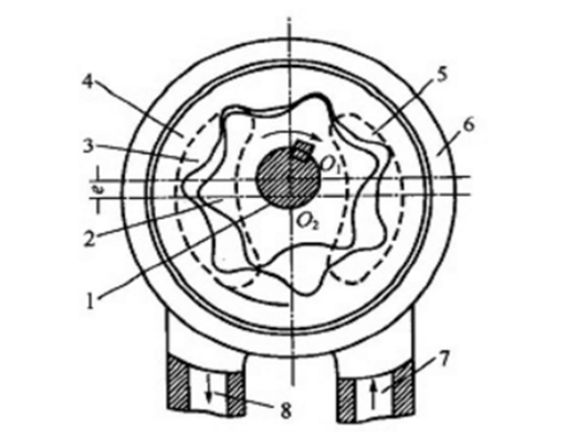
Figure 7: Working principle diagram of cycloid gear pump.
1—Transmission shaft, 2—Inner rotor; 3—Oil discharge port of oil distribution plate; 4—Outer rotor; 5—Oil suction port of oil distribution plate; 6—Shell; 7—Oil suction port; 8—Oil discharge port
During operation, all the gear teeth of the inner rotor engage. The meshing line of each two adjacent teeth, the casing and the oil distribution plates on both sides form several closed working chambers.
As the inner rotor rotates clockwise around the center O1, the outer rotor rotates in the same direction and at different speeds around the center of O2. The volume of each chamber changes.
Therefore, the oil in the chamber is sucked and pressed through the oil suction port 5 and the oil discharge port 3 of the oil distribution plate.
Like the external gear pump, the medium and high pressure cycloid gear pump adopts end face clearance compensation to improve the volume efficiency, and its maximum working pressure can reach 16MPa.
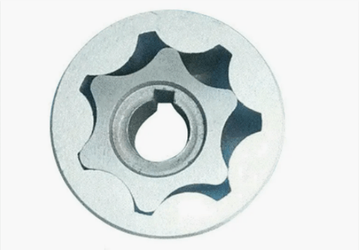
Figure 8: Cycloid gear pump.
Structural characteristics of internal gear pump: A typical internal gear pump is mainly composed of internal gears, external gears and baffles, etc. The function of the pump is completed by using the volume change formed by the teeth and the ring gear. There are suction and discharge ports arranged in axis-symmetrical positions. It cannot achieve variable displacement, the radial load is large and compared to the external meshing type, the size is slightly smaller, and the price is slightly higher.
Related Info
How Does a Hydraulic Pump Work?How to Select a Hydraulic Pump
Hydraulic Pumps: Common Faults and Troubleshooting Methods
Gear Pumps: Working Principle, Types, Pros&Cons and Applications
Common Faults and Troubleshooting of Gear Pumps
