


Figure 1: A frequency converter with digital panel.
A VFD (Variable-frequency Drive, frequency converter) is a power control device that uses frequency conversion technology and microelectronics technology to control an AC motor by changing the frequency of the motor's working power supply.
The frequency converter is mainly composed of a rectifier, inverter and so on. It adjusts the voltage and frequency of the output power supply by the switching on/off of the internal IGBT. At the same time, it provides the required power supply voltage according to the actual needs of the motor, thereby achieving the purpose of energy saving and speed regulation.
In addition, the VFD has many protection functions, such as over-current, over-voltage, overload protection and so on. With the continuous improvement of industrial automation, frequency converters have also been widely used.
1. Frequency Converter Components
The frequency converter can be divided into four main parts.

Figure 2: Diagram showing four main parts of a frequency converter and the working process.
1.1 Rectifier
A rectifier is a device that converts alternating current (AC) into direct current (DC). It can be used to power supply devices and detect radio signals. A large number of diode converters are used daily, and two sets of transistor converters can also be used to form an inverter. Because its power direction is reversible, it can be regeneratively operated. On the contrary, a device that converts direct current (DC) into alternating current (AC) is called an "inverter."
In the standby UPS (Uninterruptible Power Supply), only the battery needs to be charged, and there is no need to supply power to the load, so there is only a charger. In a double-conversion UPS, this device not only supplies power to the inverter, but also charges the battery, so it is called a rectifier/charger.
Simply to say, a rectifier is a device that converts alternating current (AC) into direct current (DC). It has two main functions. First, it converts alternating current (AC) into direct current (DC), which is filtered and supplied to the load or to the inverter. Second, it provides charging voltage to the battery. Therefore, it also acts as a charger at the same time.
1.2 Intermediate Circuit
A rectifier circuit can be used to obtain a DC voltage or a DC current from the AC power supply of the power grid. But this voltage or current contains a voltage or current ripple with a frequency six times the frequency of the power supply. In addition, the inverter circuit will also produce ripple voltage and current due to the output and carrier frequency, and in turn affect the quality of the DC voltage or current.
Therefore, in order to ensure that the inverter circuit and the control power supply can obtain high-quality DC current or voltage, the output of the rectifier circuit must be smoothed to reduce voltage or current fluctuations. This is the function of the DC intermediate circuit. And because of this, the DC intermediate circuit is also called a smoothing circuit.
For voltage-type inverters, the output of the rectifier circuit is a DC voltage, and the DC intermediate circuit smooths the output voltage through a large-capacity capacitor. For current-type inverters, the output of the rectifier circuit is DC current, and the DC intermediate circuit smooths the output current through a large-capacity inductor.
The DC capacitor used in the DC intermediate circuit in the voltage type inverter is a large-capacity aluminum electrolytic capacitor. In order to obtain the required withstand voltage and capacity, capacitors are often used for series or parallel connection according to the requirements of voltage and inverter capacity.
1.3 Inverter
Contrary to a rectifier, an inverter is a converter that converts DC power (battery, storage battery) into fixed-frequency, constant-voltage or frequency and voltage modulation AC (usually 220V, 50Hz sine wave). It is composed of inverter bridge, control logic and filter circuit. A 3-phase AC output can be obtained by turning on and off the 6 switching devices with the determined time.
In addition, the inverter itself consumes part of the power when it is working, so its input power is greater than its output power. The efficiency of the inverter is the ratio of the output power of the inverter to the input power. If an inverter inputs 100 watts of direct current and outputs 90 watts of alternating current, then its efficiency is 90%.

Figure 3: Neatly installed and arranged frequency converters.
1.4 Control Circuit
The control circuit is a circuit that provides control signals to the main circuit of the asynchronous motor (voltage and frequency adjustable). It has the frequency and voltage "calculation circuit", the main circuit "voltage and current detection circuit", the motor's "speed detection circuit", the "drive circuit" that amplifies the control signal of the arithmetic circuit, and the "protection circuit" of the inverter and the motor.
Calculation Circuit
It compares the external speed, torque and other commands with the current and voltage signals of the detection circuit to determine the output voltage and frequency of the inverter.
Voltage and Current Detection Circuit
It is isolated from the main circuit to detect voltage and current.
Drive Circuit
The circuit drives the main circuit device. It is isolated from the control circuit and controls the turning on or off of the main circuit device.
Speed Detection Circuit
It takes the signal of the speed detector (tg, plg, etc.) installed on the asynchronous motor shaft machine as the speed signal, and sends it to the calculation loop. According to the instructions and calculations, the motor can run at the command speed.
Protection Circuit
It is used to detect the voltage, current, etc. of the main circuit, in order to prevent damage to the inverter and asynchronous motor when an abnormality such as overload or overvoltage occurs.
2. Types of VFD
According to the Method of Frequency Conversion
There are two types of inverters: AC-AC and AC-DC-AC. AC-AC frequency converter can directly convert the utility frequency AC into a current whose frequency and voltage can be controlled. So it is also called a direct frequency converter.
AC-DC-AC inverter is to convert the power frequency alternating current into direct current through a rectifier, and then convert the direct current into alternating current with controllable frequency and voltage through the inverter. So it is also known as an indirect frequency converter.
According to the Nature of the DC Power Supply
According to whether the energy storage element of the DC intermediate circuit for buffering reactive power is an inductor or a capacitor, the inverter can be divided into two categories, current type and voltage type.
Performance comparison is as follows:
|
|
Voltage type |
Current type |
|
DC filter link |
Capacitor |
Inductor |
|
Output voltage waveform |
Rectangle wave |
Approximate to sine wave, voltage spikes appearing sometimes |
|
Output current waveform |
Approximate to sine wave, having a large harmonic component |
Rectangle wave |
|
Dynamic output impedance |
Small |
Large |
|
Four quadrant operation |
Inconvenient, need to install anti-parallel inverters on the power supply side |
Convenient, just adjusting the trigger angle of the converter |
|
Over current and short circuit protection |
Difficult |
Easy |
|
Thyristor conduction mode |
180° conduction type |
120° conduction type |
|
Requirements for thyristors |
Low withstand voltage, and the turn-off time should be short |
High withstand voltage, no strict requirements on off time |
|
Line structure |
More complex |
Easier |
|
Application |
Multi-machine drag, irreversible and stable operation, used in the occasions with low requirements for rapidity |
Single-machine reversible drag, used in the occasions that require frequent forward and reverse rotation, and starting and braking |
Table 1: Performance comparison between current type and voltage type of frequency converters.
Classified by Voltage Level
There are low-voltage inverters and high-voltage inverters. The voltage level of the low-voltage inverter is 380-460V, the single-phase is 220-240V, the three-phase is 220V or 380-460V and the capacity is 0.2-280-500kW. It is generally called the medium and small capacity inverter.
The voltage level of the high-voltage inverter is 3kV/6kV/10kV. There are high-voltage medium and small-capacity inverters and high-voltage large-capacity inverters.
According to the Frequency Conversion Control Method
There are the following types. The first generation uses U/F=C control, also known as sine pulse width modulation (SPWM) control mode.
The second generation uses voltage space vector control (magnetic flux trajectory method), also known as SVPWM control mode.
The third generation uses vector control (magnetic field orientation method), also known as VC control mode.
The fourth generation uses direct torque control, also known as DTC control.
The basic parameters are shown in the table below (Note: Direct torque control, with PG or encoder, “ i" can be expanded to 1:1000, and the static speed accuracy can reach ±0.01%).
|
Control methord |
U/F=C control |
Voltage space vector control |
Vector control |
Direct torque control |
||
|
Feedback devices |
Without PG |
With PG or PID adjuster |
No feedback device |
Without PG |
With PG or encoder |
No feedback device |
|
Speed ratio i |
<1/40 |
1/60 |
1/100 |
1/100 |
1/1000 |
1/100 |
|
Starting torque (at 3 Hz) |
150% |
150% |
150% |
150% |
150% at zero speed |
150%-200% at zero speed |
|
Static speed accuracy |
±(0.2-0.3)% |
±(0.2-0.3)% |
±0.2% |
±0.2% |
±0.02% |
±0.2% |
|
Application |
General fan, pump, etc |
High precision speed control |
General industrial speed regulation or control |
All speed regulation or control |
Servo drive, high precision transmission, torque control |
Heavy load starting, lifting load torque control system, constant torque fluctuation and large load |
Table 2: Four control methods of frequency converter.
Classified by Different Purposes
In addition to general-purpose inverters, there are high-performance inverters and special inverters designed to meet the different application characteristics of various industries, such as special frequency converters for subway locomotives, electric vehicles, rolling mills, elevators, heavy machinery, fans and pumps, etc.
The main differences between fan and pump inverters and general inverters are shown in the following table:
|
Performance parameter |
Fan, pump inverter |
General purpose inverter |
|
Maximum frequency (Hz) |
50-120 |
50-400 |
|
Starting torque |
>50% |
>150% |
|
Overload current |
120%, 1 min |
150%, 1 min |
Table 3: Main differences between fan and pump inverters and general inverters.
3. Application in Ordinary Life
Generally, single-phase asynchronous motors are most commonly used in household appliances, which rely on capacitors or resistors to separate the phases. The motor is often in a short-term repetitive state (on/off) when working, such as air conditioners, refrigerators, etc. This will inevitably bring a series of disadvantages such as frequent starting, high noise, short motor life, poor temperature stability, and high energy consumption.
The application of frequency conversion speed regulation technology not only brings increased functions and improved performance to these home appliances, but also has obvious energy-saving and noise-reducing effects. Meanwhile, it makes the life of the whole machine significantly longer than that of traditional home appliances.
There are many methods for asynchronous motor speed regulation, such as pole-changing speed regulation, variable-slip speed regulation and frequency conversion speed regulation. The first two kinds of slip losses are large, the efficiency is low, and they have certain limitations to the characteristics of the motor.
Frequency conversion speed regulation is to achieve motor speed regulation by changing the frequency of the stator power supply to change the synchronous frequency. In the whole process of speed regulation, it can maintain a limited slip rate from high speed to low speed, so it has high efficiency, wide speed regulation range (10-100%) and high precision performance. The power saving effect can reach 20-30%.
There are two methods of frequency conversion speed regulation: one is AC-DC-AC frequency conversion, which is suitable for high-speed and small-capacity motors. The other is AC-AC frequency conversion, suitable for low-speed and large-capacity drag systems.
3.1 Inverter Air Conditioner

Figure 4: A inverter air conditioner.
Inverter air conditioners can be divided into 3A and 3D inverter air conditioners according to the types of indoor fan motors, outdoor fans and compressors.
Inverter air conditioners whose indoor and outdoor fans and inverter compressors are all adapting to alternating current (AC) forms are generally called 3A inverter air conditioners.
For indoor and outdoor fans and inverter compressors, inverter air conditioners in the form of three-phase brushless DC motors (DCBLM) are generally called 3D inverter air conditioners.
The price of the latter is much higher than the former, and the material cost alone is higher than that of a 3A inverter air conditioner of the same power. Besides, it is more difficult to develop, and the coordination of the air-conditioning system and the controller is more complicated.
Inverter air conditioners have the advantages of rapid cooling and heating, energy-saving operation, good comfort, power saving and strong heating capacity when the outside temperature is low. Their market demand is also increasing.
3.2 Frequency Converter in Water Supply System
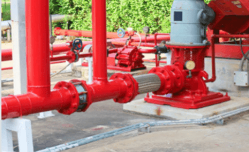
Figure 5: A part of water supply system.
With the improvement of living standards, people's requirements for domestic water are increasing. Frequency conversion constant pressure water supply has become more and more widely used in the water supply industry due to its advantages in environmental protection, energy saving and high quality of water supply.
In the past, variable frequency and constant pressure water supply often used programmable logic controllers (PLC) and frequency converters to achieve control. But the programmable technology content is high, programming is difficult, and people feel that it is not easy to master.
The use of the inverter built-in PID (Proportion Integration Differentiation) control mode can abandon the trouble of programmable debugging. It is simple and easy to learn, easy to debug, reliable in performance, and strong in anti-interference ability.
The following two kinds of sensors are generally used in variable frequency water supply systems: remote pressure gauge and pressure transmitter to detect pipeline pressure. The remote pressure gauge is a kind of resistive sensor which can feedback 0~5V DC voltage signal while the pressure transmitter can feedback 4~20 mA DC current signal.
The pressure setting unit sets the system pressure required by the user for work, and the frequency converter is the core of the entire water supply system. By changing the working frequency of the motor, it can realize the stepless speed regulation, non-fluctuation and constant pressure water supply and various functions of the motor.
