


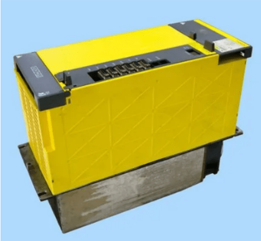
Figure 1: FANUC spindle drive.
Spindle Amplifier Alarm Codes and Solutions
The following is a continuation of the previous article, and introduces FANUC spindle drive alarm codes 74-88. Besides, other alarm codes are also introduced.
Alarm Code 74
Fault content: This alarm only occurs when double-check security is used. The CPU test did not end normally.
Troubleshooting method: Replace the SPM or SPM control printed circuit board.
Alarm Code 75
Fault content: This alarm only occurs when double-check security is used. An exception occurred in the CRC test.
Troubleshooting method: Replace the SPM or SPM control printed circuit board.
Alarm Code 76
Fault content: This alarm only occurs when double-check security is used. The safety function of the spindle amplifier has not been performed.
Troubleshooting method: Replace the control printed circuit board of the SPM.
Alarm Code 77
Fault content: This alarm only occurs when double-check security is used. The axis number check result of the spindle amplifier does not match that of the CNC.
Troubleshooting method: Replace the CNC's CPU card or the SPM's control printed circuit board.
Alarm Code 78
Fault content: This alarm only occurs when double-check security is used. The safety parameter detection result of the spindle amplifier is inconsistent with that of the CNC.
Troubleshooting method: When an alarm occurs, replace the CNC CPU card or the SPM control printed circuit board.
Alarm Code 79
Fault content: This alarm only occurs when double-check security is used. The initial test works abnormally.
Troubleshooting method: Replace the SPM or SPM control printed circuit board.
Alarm Code 81
Fault content: The per revolution signal generation position of the motor sensor is wrong.
Troubleshooting method:
(1) When using an external per-revolution signal:
(a) The parameter is wrong. Check whether the gear ratio data is consistent with the machine specification.
(b) Sliding between the spindle and the motor. Make sure there is no slippage between the spindle and the motor. External per-revolution signals cannot be applied to V-belt couplings.
(2) Troubleshooting in other situations:
(a) The parameter setting is incorrect. Please confirm the sensor setting parameters.
(b) Poor sensor adjustment (BZi, MZi sensor). Please adjust the sensor signal. If adjustment is not possible, or if the signal cannot be observed, replace the connecting cable and sensor.
(c) Poorly shielded cable between sensor and SPM. Check the shielding treatment of the cable.
(d) It is bundled with the power line of the servo motor. If the cables from the sensor to the SPM are bundled together with the servo motor power cables, bundle them separately.
(e) Poor SPM. Please replace the SPM or SPM control printed circuit board.
Alarm Code 82
Fault content: Motor sensors do not generate a per-revolution signal.
Troubleshooting method:
(a) The parameter setting is incorrect. Please confirm the sensor setting parameters.
(b) Poor sensor adjustment (BzZi, MZi sensors). Please adjust the sensor signal. If adjustment is not possible, or if the signal cannot be observed, replace the connecting cable and sensor.
(c) Bad external signal per revolution. Please observe the check pin EXTSC1 on the spindle check board. If the signal is not generated every turn, please replace the connecting cable and proximity switch.
(d) Poor SPM. Please replace the SPM or SPM control printed circuit board.
Alarm Code 83
Fault content: The SPM checks the pulse counts of the A and B phases every time a one -rotation signal is generated, and if it is not within the specified range, an alarm occurs.
Troubleshooting method:
(1) An alarm occurs when the cable is touched (spindle movement, etc.)
The wire may be broken, please replace the cable. If cutting oil penetrates into the connector part, please clean it.
(2) Troubleshooting in other situations, please see Alarm Code 81 troubleshooting (2).
Alarm Code 84
Fault content: Spindle sensor signal disconnection.
Troubleshooting method: See Alarm Code 73 for troubleshooting of this alarm.
Alarm Code 85
Fault content: The per revolution signal generation position of the motor spindle is incorrect.
Troubleshooting method: See Alarm Code 81 for troubleshooting of this alarm.
Alarm Code 86
Fault content: The spindle sensor does not generate a signal per revolution.
Troubleshooting method: See Alarm Code 82 for troubleshooting of this alarm.
Alarm Code 87
Fault content: The spindle sensor signal is abnormal.
Troubleshooting method: See Alarm Code 83 for troubleshooting of this alarm.
Alarm Code 88
Fault content: Radiator cooling fan stops.
Troubleshooting method: Replace the SPM radiator cooling fan.
Alarm Code A, A1, A2: Control Program Not Working
Fault content: An error was detected in the processing of the control program.
Troubleshooting method:
(1) This alarm is displayed when the spindle amplifier is powered on:
(a) Different software specifications.
(b) Defective printed circuit board.
Please replace the SPM or SPM control printed circuit board.
(2) The alarm occurs during motor excitation:
(a) Influence of noise. Please check the GND related wiring. If the signal cable of the spindle sensor and the power cable of the servo motor are bound together, please bind them separately.
Alarm Code B0
Fault content: Communication between amplifier modules (SPM, SVM, PSM) is abnormal.
Troubleshooting method:
(1) When this alarm is displayed immediately after turning on the power of the CNC.
(a) Please confirm the connection part of the connector. CXA2A and CXA2B are connected together for the correct state.
(b) Defective cable. Please confirm the connection pin number and correct it if there is a problem, or replace the cable.
(c) Poor SPM, SVM or PSM. Please replace the SPM, SVM, PSM or their control printed circuit boards.
Alarm Code C, C1, C2
Fault content: The serial communication data between the CNC and the spindle amplifier module is abnormal.
Troubleshooting method:
(a) Poor SPM. Please replace the SPM or SPM control printed circuit board.
(b) Defective CNC. Please replace the serial spindle related board or module.
Alarm Code C3
Fault content: During spindle switching, the internal states of the switching request signal (SPSL) and the motor/spindle sensor signal switching circuit (auxiliary module SW) do not match.
Troubleshooting method: The auxiliary module SW (SSW) is faulty, and please replace the auxiliary module SW (SSW).
Other Alarm Code
(1)When the 4, 11, 30, 33, 51, 57, 58, b1, b2, b3 alarms occur in the status display of the SPM, it means that an alarm occurs in the PSM. Check the status display of the PSM and refer to Section II.3.1 (B-85285CM).
(2) About CNC alarms 756 and 766 (abnormal axis number)
This alarm only occurs when the double-check safety function is used. When this alarm occurs, check whether K76 is attached to the connector JA7A of the 2nd spindle. If it is only the 1st spindle, K76 is not required. When there is no problem with the wiring, please replace the control PCB of the SPM.
Related Info
FANUC Common Fault Alarm AnalysisFANUC Spindle Amplifier Alarm Codes and Solutions (1)
FANUC Spindle Amplifier Alarm Codes and Solutions (2)
FANUC Spindle Amplifier Alarm Codes and Solutions (3)
