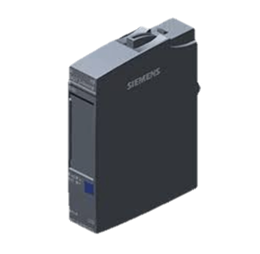
Figure 1: A PLC (Programmable Logic Controller).
(Go to Okmarts and pick the PLC you need)
PLC analog inputs usually use voltage signals in the range of 20 volts and current signals in mA. Each PLC manufacturer has I / O modules to process these types of signals, as well as other more professional modules.
1.Voltage Mode Analog Input
This mode uses a simple circuit to convert the position of 0 to a signal of 0 to 5 volts and connect it to the general PLC voltage analog input. When the PLC input be 0, while at the other end, the PLC will see 5 volts. The result of the voltage conversion to digital seen by the PLC program depends on the PLC and its configuration. In general, newer models of PLCs will provide greater flexibility in the return value so that you can scale values according to the needs of your application.

Figure 2: PLC input mode.
The PLC can use this input mode to control brightness of the bulb, the output of heat source, the speed of motor, or how fast the counter counts.
2.Current Mode Analog Input
Although the voltage input mode can meet our needs in general applications, due to the interference of electrical noise from other equipment, current mode signal transmission is a better choice for signals that need to be transmitted over any actual distance. For this reason, many applications use current input mode analog input. Current mode interface is generally as a voltage mode interface with high-precision resistance. The resistor is usually located inside the PLC module and connected through jumper or connection position.
Since there is a limit to the available voltage in the loop, people usually limit the total resistance at the measuring end of the loop to 500 ohms. This is used as a part of the field equipment installation instructions.
Some common types of analog devices use 4 to 20 mA signals as their power supply reducing the complexity required in the field unit.
3.Thermocouple Mode Analog Input

Figure 3: Thermocouples.
This type of device produces a small signal in the millivolt range. The thermocouple measurement module is designed to process these small signals into temperature readings.
The wires used to connect thermocouples to the module must be specially made for this type of thermocouple. The wrong wire will make the signal useless. Because the signal voltage is so low, it is necessary to shield the wire well and keep it away from high-voltage wires.
4.RTD Mode input

Figure 4: RTD (Resistance Temperature Detector).
Newer RTDS (Resistance Temperature Detector) are generally stronger and more accurate than thermocouples, but older sensors are still common because they are designed in older equipment. And they can operate in temperature ranges that RTDS cannot handle (up to white 1600 ℃) in unique applications. The resistance of the device changes with temperature, so the measurement output is relatively simple.
Related Info
What is a solenoid valve10 matters when installing water solenoid valve
Working principle of 5 kinds of solenoid valves


