


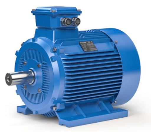
Figure 1: Industrial electric motor.
1. What is Three Phase Induction Motor
Three-phase induction motor is an AC motor that generates electromagnetic torque to drive the rotor to rotate by the interaction of the rotating magnetic field formed by the stator winding and the magnetic field of the induced current in the rotor winding.
Three-phase induction motors are mainly used in computer peripheral equipment, lathe systems, photoelectric combination devices, valve control systems, nuclear reactors, surface grinders, CNC machine tools, automatic winding machines, electronic clocks and medical equipment.
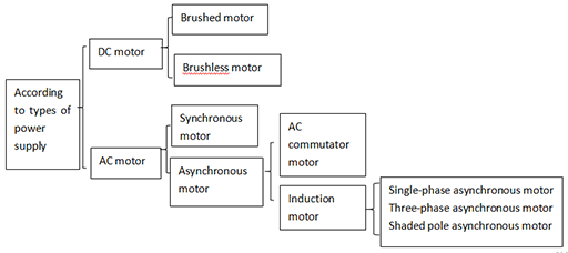
Figure 2: Types of electric motor.
1.1 Structure of the Three-phase Induction Motor
1.Stator part
(1) Stator core: It is composed of silicon steel sheets with good magnetic permeability - the magnetic conductivity part.
(2) Stator winding: placed in the inner groove of the stator core - the conductive part.
(3) Machine base: used to fix stator core and end cover, with strong mechanical strength and rigidity.
2. Rotor part
(1) Rotor core: It is made of silicon steel sheets and is also a part of the magnetic circuit.
(2) Rotor winding:
1) Squirrel-cage rotor: A bare bar is inserted into each slot of the rotor core to form a multi-phase symmetrical short-circuit winding.
2) Wound rotor / slip ring rotor: The rotor winding is a three-phase symmetrical winding, which is embedded in the rotor core slot.
3. Other parts
Including end caps, fans, etc. In addition to the protective role of the end cover, the end cover is modified with bearings to support the rotor shaft. Fans are used for ventilation and cooling.
Three-phase induction motors are classified according to the rotor structure: squirrel cage induction motors and wound rotor induction motors.
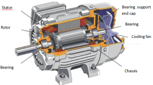
Figure 3: Inner structure of the three-phase asynchronous motor.
1.2 Main Series of Three-phase Induction Motors
There are many types of induction motors, and some common product lines are listed below.
Y series is a small cage type fully enclosed self-cooling three-phase asynchronous motor, used for metal cutting machine tools, general machinery, mining machinery, agricultural machinery, etc. It can also be used to drag machinery with large static load or inertial load, such as compressors, conveyor belts, grinders, hammer hangers, pulverizers, small cranes, transportation machinery, etc.
JD02 series is a series of small three-phase multi-speed induction motors, mainly used for various machine tools and lifting equipment.
JQ2 and JQ02 series are asynchronous motors with high starting torque, which are used to start machines with large static loads or inertial loads. JQ2 is a protective type and JQ02 is a closed type.
JS series is a medium-sized protective three-phase squirrel cage asynchronous motor.
JR series is a protective three-phase wound asynchronous motor. It is used in production machinery which has small power supply capacity and cannot be started by squirrel-cage motors of the same capacity.
JSL2 and JRL2 series are three-phase asynchronous motors for medium-sized vertical water pumps, of which JSL2 is a squirrel cage type and JRL2 is a winding type.
YR series is a large three-phase wound rotor induction motor series, mainly used in metallurgical industry and mines.
2. How Does a Three Phase Induction Motor Work
2.1 Rotation Principle of Three-phase Induction Motor
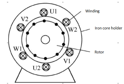
Figure 4: Three sets of windings with a difference of 120° for a three-phase motor.
1. Electricity generates magnetism. The three-phase symmetrical winding leads to the three-phase symmetrical current to generate a circular rotating magnetic field.
2. Magnetism generates electricity. The rotating magnetic field cuts the rotor conductor to induce electromotive force and current.
3. Electromagnetic force: The rotor current-carrying (active component current) body is subjected to electromagnetic force under the action of the magnetic field, forming electromagnetic torque, driving the motor to rotate, and converting electrical energy into mechanical energy.
For example, the three-phase induction motor has three-phase symmetrical windings embedded in the stator slots, and bars are placed in the rotor slots. The ends of all bars are short-circuited with two short-circuit rings to form a closed rotor winding.
If the rotor speed is zero at the beginning, the rotor bar cutting the rotating magnetic field will generate an induced electromotive force e2. Since the rotor bar is short-circuited, a short-circuit current i2 will appear in the rotor conductor.
The rotor current i2 interacts with the air-gap magnetic field, which will generate an electromagnetic force whose direction is determined by the left-hand rule.
The torque produced by the electromagnetic force is called electromagnetic torque. Under the action of electromagnetic torque, the rotor will rotate in the direction of the rotating magnetic field.

Figure 5: The connection between the terminals of the junction box and the internal winding for three-phase induction motor.
Since the electromotive force and current on the rotor side are generated by electromagnetic induction, this type of motor is called an induction motor. In addition, if the rotor speed is the same as the synchronous speed of the rotating magnetic field, there will be no induced electromotive force in the rotor bar, and there will be no electromagnetic force and electromagnetic torque. Therefore, when the induction motor is running normally, there is always a difference between the rotor speed and the rotating magnetic field speed, so the induction motor is also called an asynchronous motor.
2.2 Slip of Three-phase Induction Motor
The ratio of the difference between the synchronous speed and the rotor speed to the synchronous speed is called slip, which is represented by “s", namely:
s=(n1-n)/n1
Where,
n1--synchronous speed (speed of rotating magnetic field)
n--rotor speed (speed of motor)
s--slip
Slip is a basic physical quantity of asynchronous motor, which reflects various operating conditions of the motor. The greater the load, the lower the speed, and the greater the slip; on the contrary, the smaller the slip. The size of the slip rate can reflect the speed of the motor or the size of the load. The speed of the motor is:
n=(1-s)n1
3. Speed Regulation of Three-phase Induction Motor
In recent years, with the rapid development of power electronics technology, microelectronic technology, computer technology and automatic control technology, the speed regulation technology of three-phase induction motor has also developed rapidly and has become more and more perfect. In industrial applications, any occasion where a DC motor can be used for speed regulation can be switched to AC speed regulation.
Since induction motors generally do not have commutators, they can be made into large-capacity, high-speed, and high-voltage speed control systems that cannot be achieved by DC motors. In addition, for most fans and pumps that do not require speed control, after adopting AC speed regulation, energy can be greatly saved. So the research on speed regulation and energy saving of induction motors is of great significance.
By the speed formula of the induction motor:
n=ns(1-s)=[(60f1)/p](1-s)
Where,
ns--synchronous speed
n--rotor speed
s--slip
f1--power supply frequency
p--number of pole pairs
It can be seen that to change the speed n of the induction motor, the following three methods can be used:
(1) Pole-changing speed regulation. Change the number of pole pairs p to change the synchronous speed ns of the stator rotating magnetic field to achieve speed regulation.
(2) Frequency conversion speed regulation. Change the power supply frequency f1 to change the synchronous speed ns of the stator rotating magnetic field to achieve speed regulation.
(3) Variable slip speed regulation. The speed regulation is realized by changing the slip rate s of the motor. It is divided into the methods of lowering the stator voltage, connecting resistance to the rotor circuit and cascade speed control.
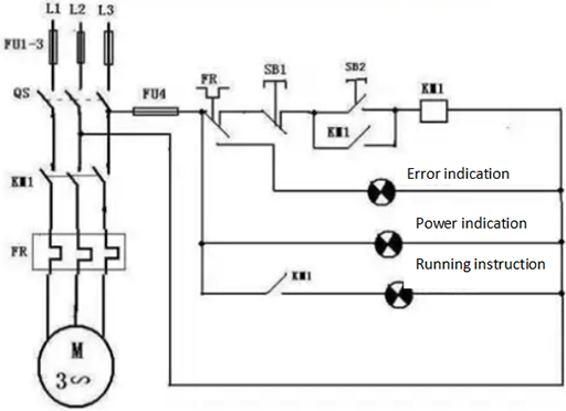
Figure 6: Three phase induction motor circuit diagram.
4. Advantages of Three Phase Induction Motor
1. Three-phase induction motor has international interchangeability. It adopts the international standard size formulated by IEC (International Electrotechnical Commission), which is internationally interchangeable.
2. Excellent characteristics: due to the small inertia of the rotating part, the large acceleration torque, and the short start and stop time, it can improve the working efficiency of the machine that starts and stops frequently.
3. Low vibration and noise: The mechanical structure is perfectly designed, the processing and assembly are excellent, and after precise balance, there is almost no vibration and noise.
4. Easy maintenance: high-grade oil-sealed bearings are used, and there is no need to add lubricating grease, which is convenient for maintenance.
5. Small and lightweight: the frame size is reduced, and the body is small and light, space-saving, easy to carry and install, and convenient for design and construction.
6. E/B/F grade insulating material: E/B/F grade insulating material with heat resistance, moisture resistance and chemical resistance is adopted, which is safe and durable and has the longest service life.
Related Info
FANUC Spindle Amplifier Alarm Codes and Solutions (1)FANUC Spindle Amplifier Alarm Codes and Solutions (2)
FANUC Spindle Amplifier Alarm Codes and Solutions (3)
FANUC Spindle Amplifier Alarm Codes and Solutions (4)
Brushless Vs Brushed Motor
